A variable power supply is one of the most important pieces of equipment to have on the electronics workbench. It's only a matter of time before the voltage or current required in a circuit isn't practical for battery power.
Bench-top variable power supplies available today are typically transformer-fed linear voltage regulators which are both simple and inexpensive to manufacture. However these supplies are also large, heavy, and inefficient for most of their output voltage range. Many linear designs cannot operate anywhere near their rated output current when large Vo-Vi is required, but for low power applications they provide stable and noise free output.
Switched-mode power supplies are more than 90% efficient through almost the entire output voltage and current range, require much less space for heat sinks and transformer cores (90% less in medium to high current designs), and are as much as 5 times lighter than an equivalent linear power supply. But these advantages come at the expense of ripple, noise, and transient response; the three parameters that linear power supplies excel at.
I was working with some high power LED designs recently that required 2.5V to 9V and forward current between 1 Amp and 2 Amps. My LM317-based lab supply couldn't run more than a few minutes without tripping the thermal overload due to VI and Pmax limitations. This was a pretty hefty supply but it was getting too hot to operate reliably. So I decided to build my own 100W dual variable switched supply that could drive 2 Amps at an output voltage between 1V and 20V.
I wanted the regulation specifications to be competitive with the LM317 but my application did not require an extremely low ripple/noise figure. Current limiting and overload protection were important so independent voltage and current adjustments were required. And it would be nice to include a V/I meter for each supply for convenience.
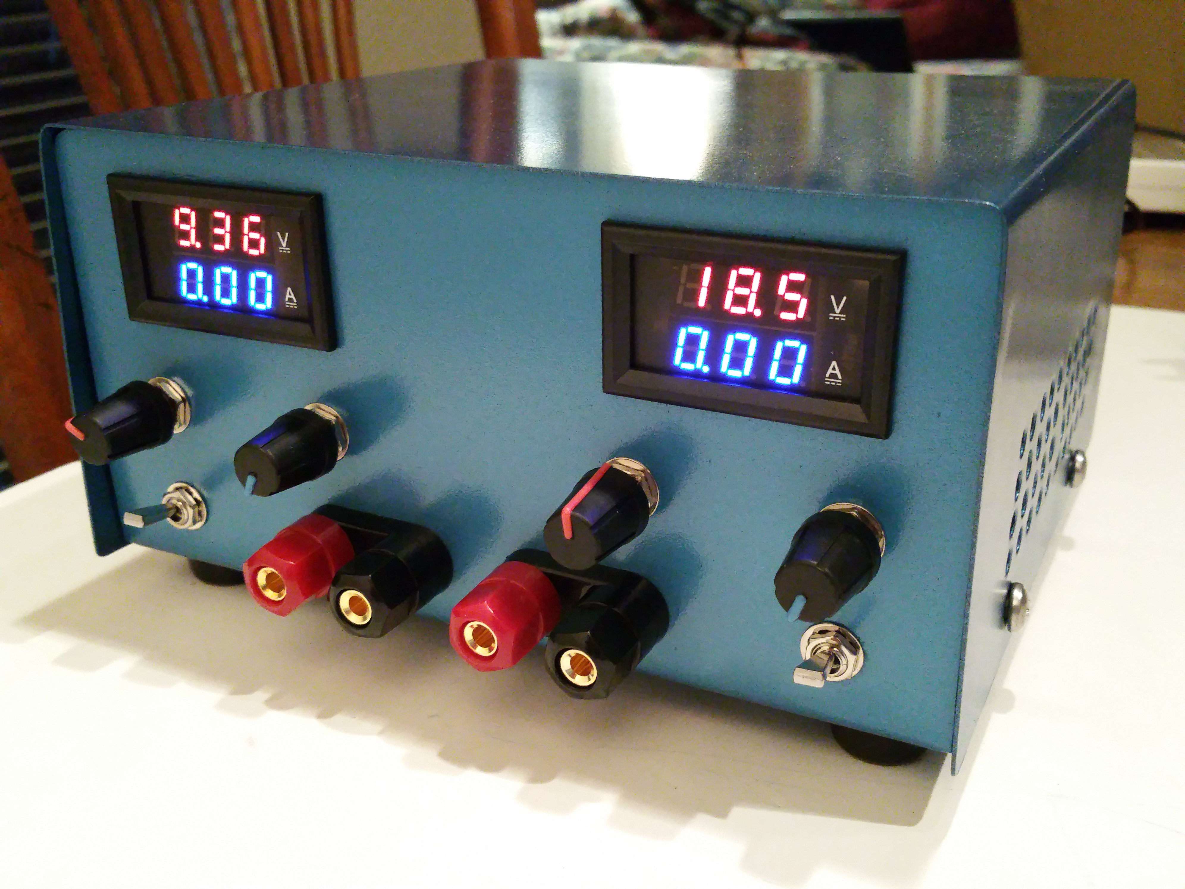
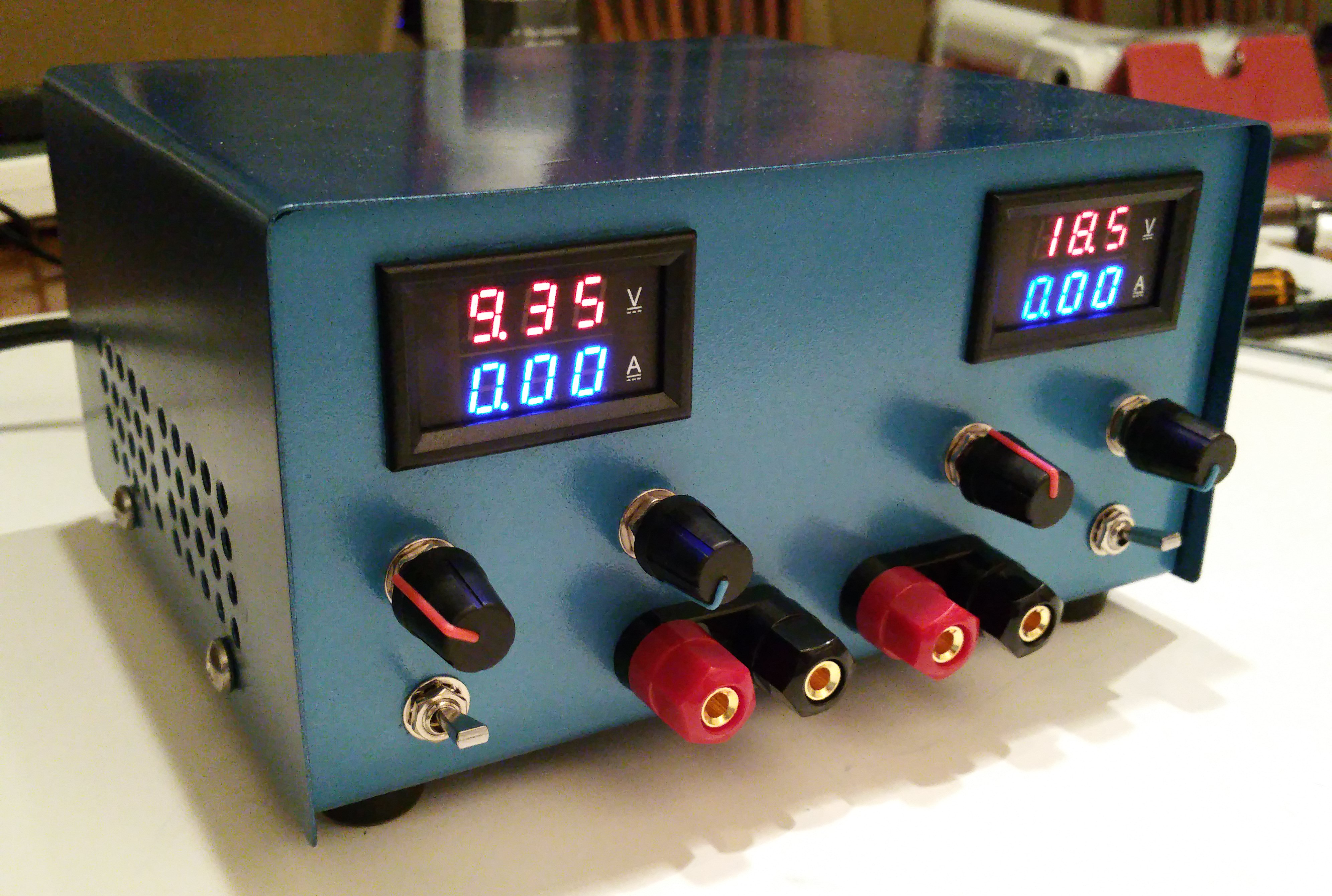
This project will illustrate how to construct the 100W dual output switched mode variable power supply I have for about $150 using off-the-shelf modules and a prefabricated enclosure available on amazon.com or ebay.com. This power supply is compact, weighs less than 3 lbs, and deliverers professional appearance and performance competitive with commercial switched power supplies.
I've used this supply for a lot of heavy duty circuits including a DC motor controller and a 50W prototype audio amplifier with great results. I would not recommend this supply for precision Op-Amp or Radio Frequency circuits but for just about everything else it has worked really well.
Review the Power Supply Design
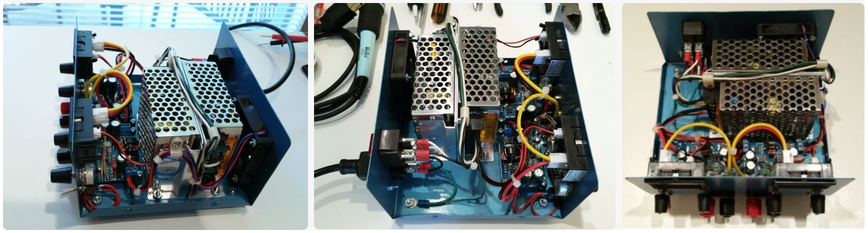
The Switched Mode Variable Power supply was designed using off-the-shelf modules that could be wired together using simple tools and basic soldering and wiring techniques. Two modules require modification so that front panel controls can be used instead of the PCB mounted multi-turn potentiometers included with the modules. These modifications are covered in a later step.
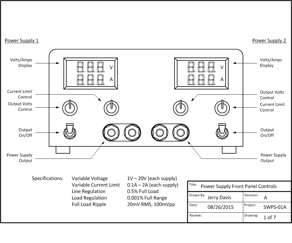
Power Supply Specifications
Input: 120VAC (+/- 15%) 60Hz 1A Full Load
Output 1: 1.2V - 20V @ 2 Amps
Output 2: 1.2V - 20V @ 2 Amps
Load Regulation: 0.5% Full Load
Line Regulation: .001% Full Input Range
Noise/Ripple: 20mV RMS, 100mVpp
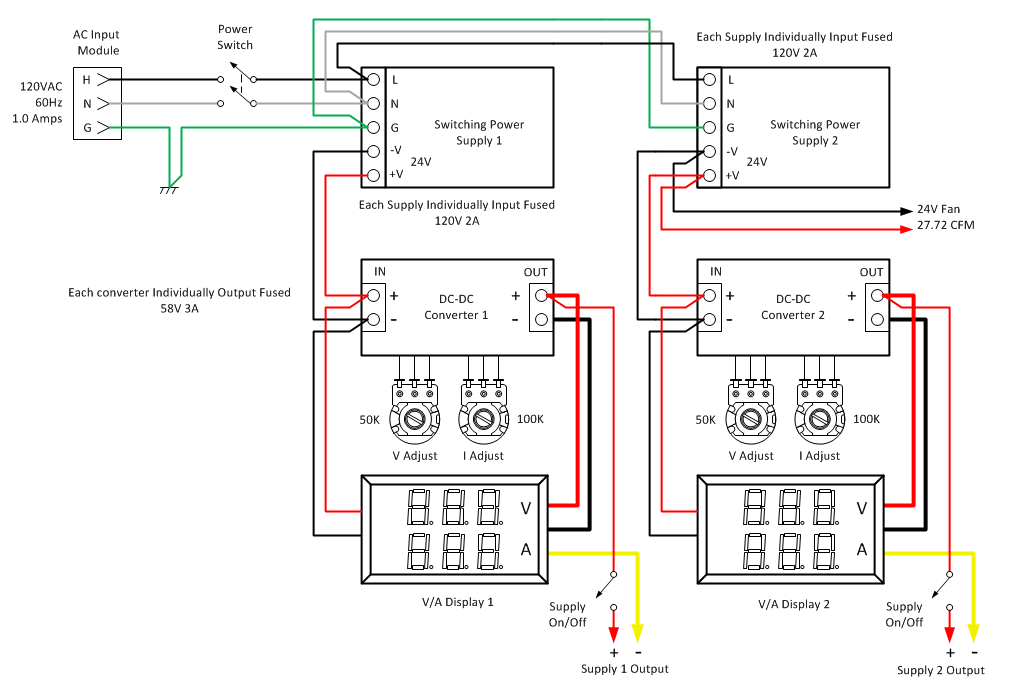
General Circuit Description
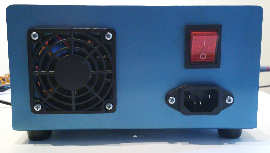
AC power is connected to the supply via an IEC 320-C13 AC input module. AC safety ground is bonded to the power supply case and feed through to switching power supplies 1 and 2. The case of the power supply is grounded to the AC mains circuit. DC output ground is electrically isolated and independent of the AC mains ground.
Switching power supplies 1 and 2 are energized and de-energized through an illuminated DPST power switch. These supplies provide the constant 24V DC needed for DC-DC converters 1 and 2, the cooling fan, and the V/I displays. DC-DC converters 1 and 2 provide controlled output voltage and current to the power supply binding posts.
The output voltage and current set points are determined by two 50K Ohm and two 100K Ohm single-turn potentiometers. The DC positive power connection can be disconnected from the circuit by flipping the output power switch to the off (Down) position.
Two panel meters provide direct readout of the voltage set point and the current being consumed by the circuit attached to each power supply. The panel meters use a shunt type current sensor inline with the DC ground conductor. Power for each meter (< 20mA each) is taken directly from the 24V switching power supplies.
All power supplies are current and thermal overload protected and include last resort short circuit protection via fuses on switched power supply AC input and converter DC output. Cooling for the power supply is forced air via a 27 CFM fan using 24V @ 100mA drawn from switching power supply 2.
Design Tradeoffs
In order to keep total cost around $150, single-turn potentiometers were used instead of precision multi-turn potentiometers. Setting the output voltage is easier with 10-turn precision pots but a well made set would have increased the cost of the supply by $40. I decided to live with the fiddly nature of a general purpose single-turn pot for setting the output voltage. My applications do not require exact voltages. Close enough is good enough.
In order to keep costs low and simplify module wiring, I did not use DC-DC converters with an external voltage sense feature. This results in a slight degradation in load regulation (0.5% instead of 0.1%) due to the current shunt used in the current meter.
The 60mm x 60mm fan I used is overkill for this design and a bit louder than I would have liked. Lower CFM fans from Delta Electronics were non-stocked at Mouser so I decided to accept the overkill. With the supply installed on the instrument shelf I hardly notice the fan noise among all the other fan noise going on in the lab.
The current limit control is usable for only about half of it's range due to the 5A current rating of the DC-DC converter. I could have used two resistors to scale the current control to use the full rotation but did not feel the wiring complexity was worth the effort. I usually start with minimum current on a new circuit and slowly increase the current limit until a stable output voltage is achieved. I might add the scaling resistors at a later time if I think it's needed.
A full size PDF file for all Power Supply diagrams and parts list can be downloaded >>> HERE <<<.
Review the Parts List
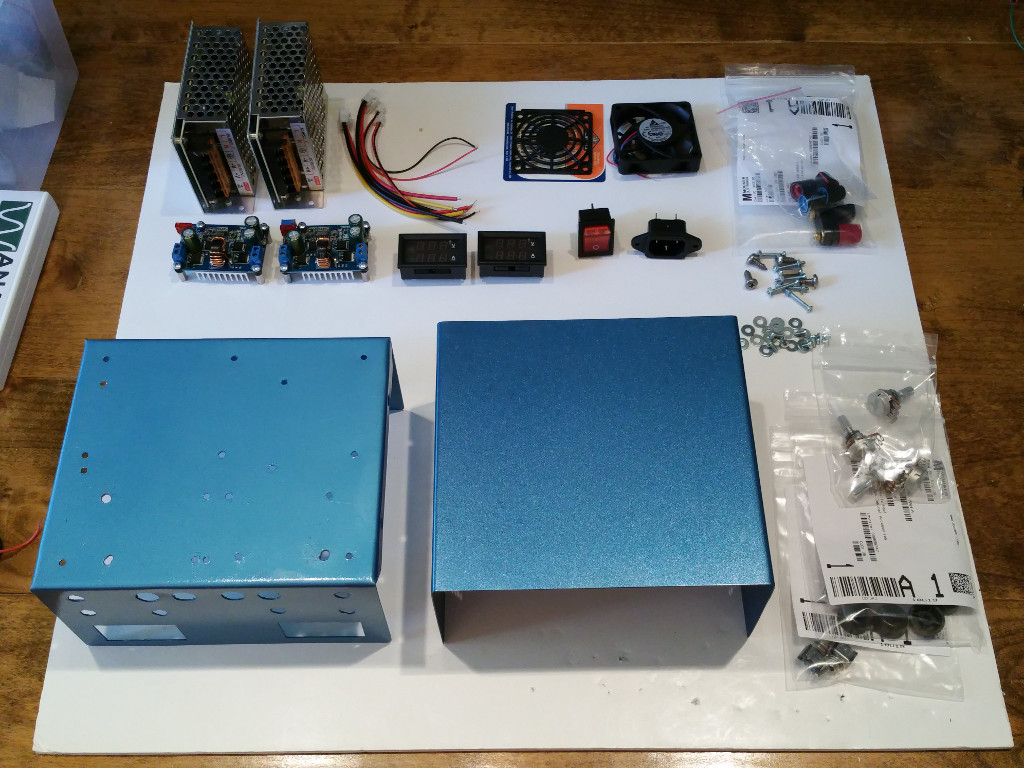
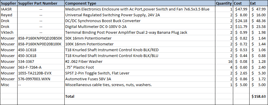
Obtain the parts listed for the power supply project. Everything can be purchased from Amazon, eBay, and Mouser as of August 2015. All prices are current as of August 2015.
I keep an inventory of plastic cable ties and a variety of screws, nuts, and washers. I used a few of these in the finishing of the power supply and didn't list them in the parts list because their single unit cost is extremely low. Have on hand some 4" cable ties and a few pieces of #6 and #10 screws/nuts/washers.
With respect to the IAASR SimCase product there are a number of options available on the iaasr.com website. Be sure to choose the color you want, select fan/power/ac-input, and choose the 24V fan option.
Please Note: I have no business relationship with any of the vendors in my parts list. Nothing of financial value was exchanged for my recommendation. None of the above vendors provided compensation of any kind during the creation of this project. I will not be compensated in any way if you choose to build this project or purchase components from any vendor I recommend. I simply had a good experience with the vendors I recommend and believe you will too.
A full size PDF file for all Power Supply diagrams and parts list can be downloaded >>> HERE <<<.
A Word About Electronics Enclosures

NOTE: As of 2026 IAASR is no longer in business. I have left the content here in place for historical reasons. I have provided detailed construction drawings for the case in the "Prepare the Enclosure" section below.
I love to see a useful project professionally finished in a nice enclosure. A well designed enclosure improves the durability and appearance of a DIY project and enhances the "I made that" pride in craftsmanship a builder earns from the work. However, many builders have the following complaints with the enclosure products available on the market today:
1. Project boxes cost more than the value they add, and sometimes more than the parts they enclose.
2. Poking holes of various shapes and sizes in an enclosure is hard work. If not done properly, the appearance of an expensive enclosure can be destroyed.
3. Designing the front and back panel layout is time consuming and not as much fun as designing and building the circuit.
4. It's difficult to find an enclosure that is the right size and shape for a particular type of project.
When I started looking for an enclosure for the dual switch-mode power supply project, I was shocked at the prices manufacturers were asking for a simple project case. The basic grey on grey cabinet without a single hole cut in it was $100 and up! If I was going to spend that kind of money, I better have a fully equipped machine shop to do the job right. But then the sizes available were either too large or too small, too deep or too tall. I didn't want unpainted aluminum or battleship grey. None of the manufacturers in Mouser or Digikey had anything that fit my design in an affordable, easy to build way.
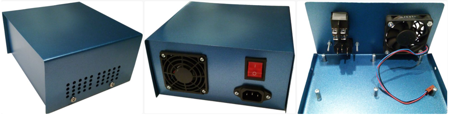
While searching through Amazon and eBay I happened to discover IAASR and their line of SimCase and HexCase enclosures. These are purpose-built enclosures with holes already cut and parts already installed for specific use-cases. When I saw the IAASR SimCase I said "That's exactly what I need!". The SimCase product is designed by IAASR to house a DIY power supply. It includes an EMI shielded mild steel enclosure, the AC input module, an illuminated AC power switch, a fan, and ventilation holes validated with thermal analysis software... for $49. That's a layout I didn't have to design, parts I didn't have to research and order, and holes I didn't have to cut which would save me a huge amount of time. IAASR offers their enclosures in 5 standard colors and 15 custom colors which means your project can look cool like you imagined it would instead of like a low-bid government job.
But that's not all. I contacted Shiraz Macuff, CEO, about the front panel design. He says, "Send me a layout and we'll cut the holes before we ship at no extra charge". That's service you can only get when you order quantity 10,000 from any other manufacturer. I ordered quantity one from IAASR. It turns out that IAASR is disrupting the enclosure market with purpose-built products that save time, add value, and can be mass-customized to meet the requirements of the DIY, prototype, and small-medium volume manufacturer. IAASR enclosures can make your DIY project seem more like a professionally designed kit. And you don't have to worry about accidentally mutilating your enclosure with a power drill.
In this article, I am including the design drawings and assembly steps for a generic enclosure. But I strongly encourage you to use the IAASR SimCase product indicated in the parts list instead of trying to make do with the generic cases sold elsewhere. You will enjoy the building experience much more when you can focus on the assembly work and not have to put up with the dull, dirty, and sometimes dangerous fabrication work. Shiraz and his team can save you a lot of time.
Please Note: I have no business relationship with IAASR of any kind. Absolutely nothing of any financial value (money, product, gift cards, work for free, etc.) is exchanged between IAASR and I (or anyone associated with me) if you choose to buy from them. I'm recommending them because I like their product and the support I have received has been excellent. IAASR saved me a lot of time building this project and I think you will be happy with them as well.
Prepare the Enclosure
The power supply project described in this article requires an enclosure with the following minimum dimensions:
7" Wide x 3.5" High x 6" Deep
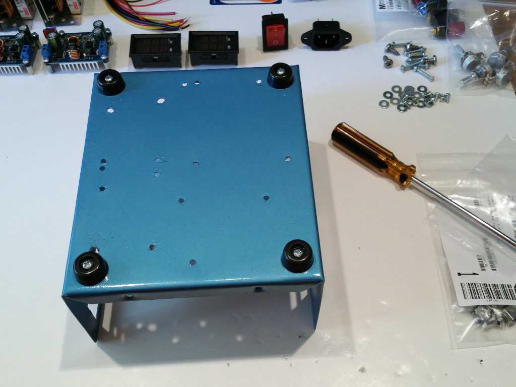
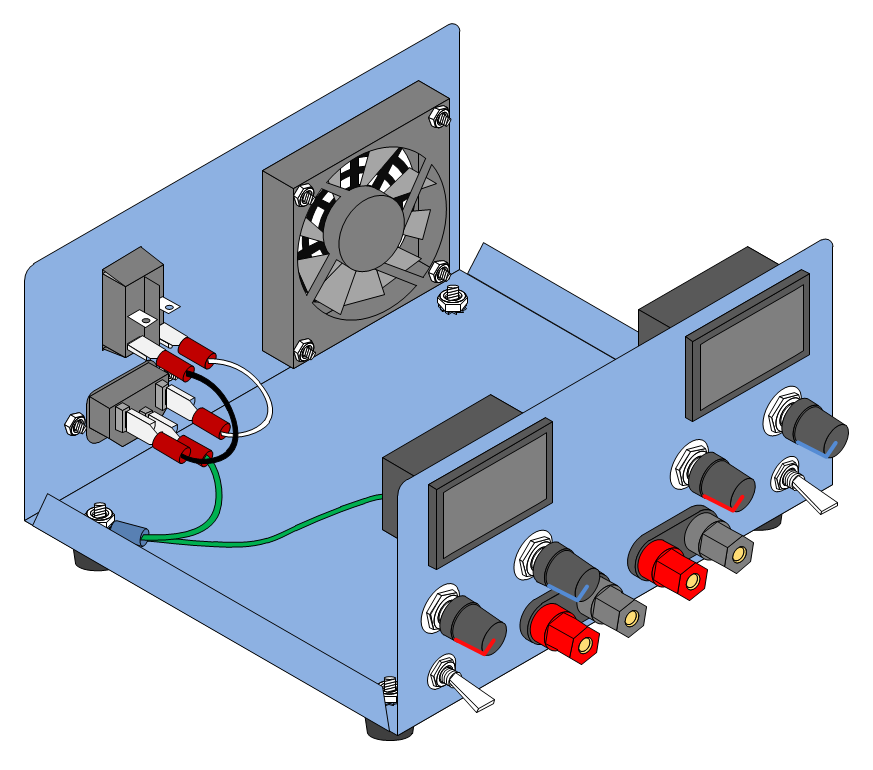
Although the enclosure can be constructed of any rigid material (plastic, aluminum, etc.) I recommend using a material that can provide some EMI shielding and AC ground fault protection. In this design I used a painted steel enclosure from IAASR which had the holes cut and AC input, AC switch, and fan already installed. I removed the components for illustration purposes showing the product being fully assembled.
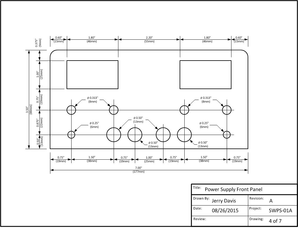
Attached below are the detailed shop drawings needed to fabricate the enclosure front, back, and bottom panels.
The shop drawings are full-scale and can be used as a template for transferring the layouts to the enclosure. When cutting holes, I strongly recommend protecting the panels with two layers of painters tape to prevent accidental scratches and tool marks from marring the finish.
If using a power drill for round holes, be sure to use a thick piece of wood at the back to avoid bending/cracking the panel and to act as a drill stop. Square openings can be cut and smoothed out with a Dremel tool cutoff wheel. Curved openings in steel can be rough cut with a Dremel tool cutoff wheel and finished up with a Tungsten Carbide cutter.
If you purchase the SimCase enclosure from IAASR you can skip this step.
A full size PDF file for all Power Supply diagrams and parts list can be downloaded
>>> HERE <<<.
Install the Case Feet
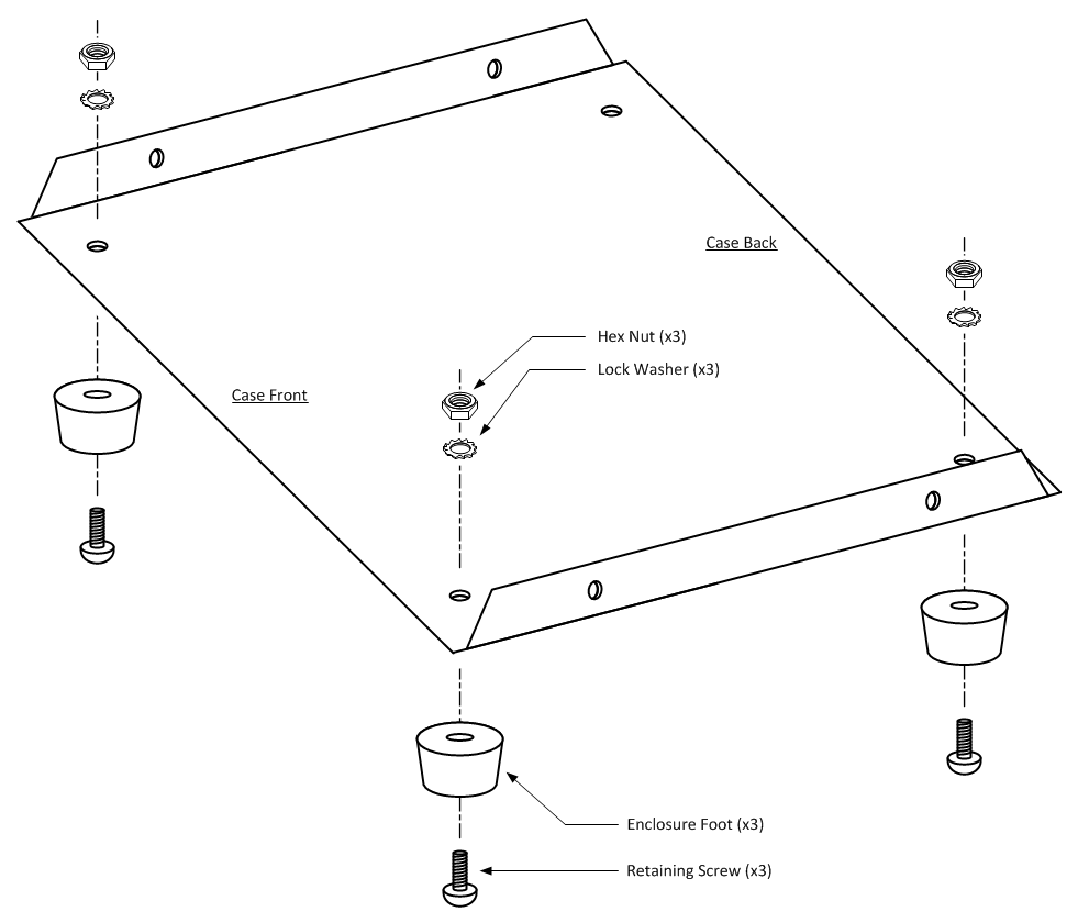
1. Remove the plastic case feet from the package and verify all mounting hardware is present.
2. Install three plastic feet as shown in the illustration above. Do not install the left rear foot (next to the AC input module position) yet.
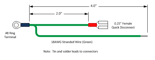
3. Cut one piece of green #18 AWG wire 2" long, and one piece of green #18 AWG wire 4" long. Strip and tin 1/4" from each wire end.
4. Insert one end of the 2" and 4" green wire into a #8 Ring Terminal and solder the wires to the terminal.
5. Solder a 0.25" Female Quick Disconnect connector to the free end of the 2" green wire.
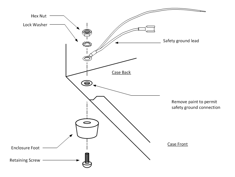
4. Scrape off the paint inside the case around the foot screw hole so that the ground cable ring terminal makes metal-to-metal contact with the case.
5. Install the last plastic foot as shown in the illustration below making sure that the ground cable ring connector is installed first, then the lock washer, and finally the hex nut.
Install the AC Input Module
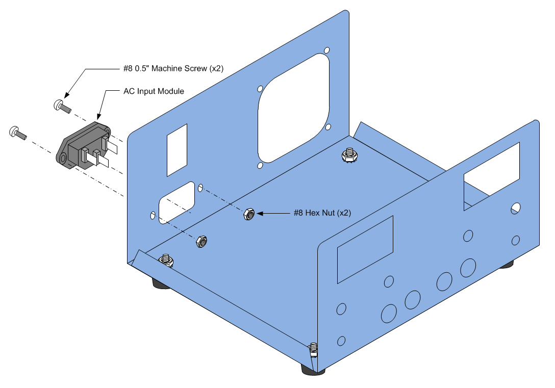
Note: If you purchased a case from IAASR the AC Input Module is already installed. Skip to the next step.
1. Insert the AC Input Module oriented as illustrated in the diagram above.
2. Fasten the AC Input Module to the case with two #8 machine screws and hex nuts.
3. Firmly tighten the machine screws but do not over-tighten.
For reference, the AC Input Module datasheet is included <<HERE>>.
Install the AC Power Switch
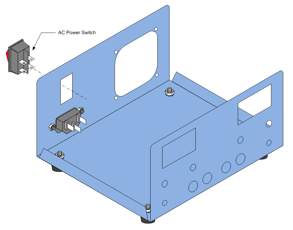
Note: If you purchased a case from IAASR the AC Power Switch is already installed. Skip to the next step.
1. Insert the AC Power Switch as illustrated in the diagram above.
2. Push the AC Power Switch into the case cutout until the top and bottom retaining clips snap into place.
Install the Cooling Fan
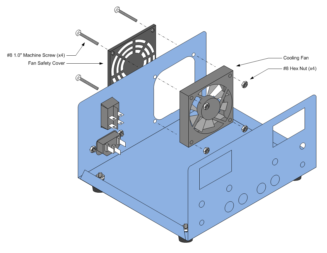
Note: If you purchased a case from IAASR the Cooling Fan is already installed. Skip to the next step.
1. Hold the fan cover against the outside fan opening and thread a single #8x1" machine screw through the cover and into the case.
2. Determine the direction of fan flow from the datasheet and orient the fan so that it's exhaust side is facing the fan cover.
3. While holding the screw in place, slide the fan (wire leads facing up) over the machine screw and thread a #8 hex nut onto the screw until both the fan cover and fan are held loosely against the case.
4. Line up the cover and fan so that each machine screw can be threaded through the cover and fan.
5. Insert the remaining three machine screws through the cover and fan.
6. Thread a #8 hex nut onto each machine screw until all four corners of the cover and fan are held loosely in place against the case.
7. Tight each machine screw until firm. Do not over-tighten.
For reference, the fan datasheet is included >>> HERE <<<.
Wire AC Input, AC Switch, and Ground
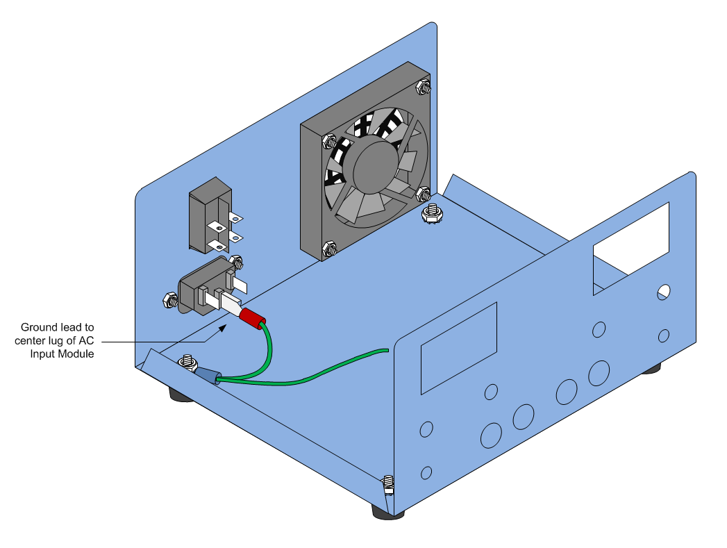
1. Connect the ground lead quick disconnect to the center lug of the AC input module as illustrated in the diagram above.
2. Cut one piece of white #18 AWG wire 1.5" long, and one piece of black #18 AWG wire 1.5" long. Strip and tin 1/4" from each wire end.
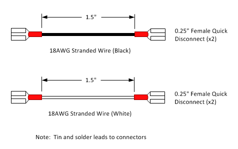
3. Solder two 0.25" Female Quick Disconnect connectors to the black wire.
4. Solder two 0.25" Female Quick Disconnect connectors to the white wire.
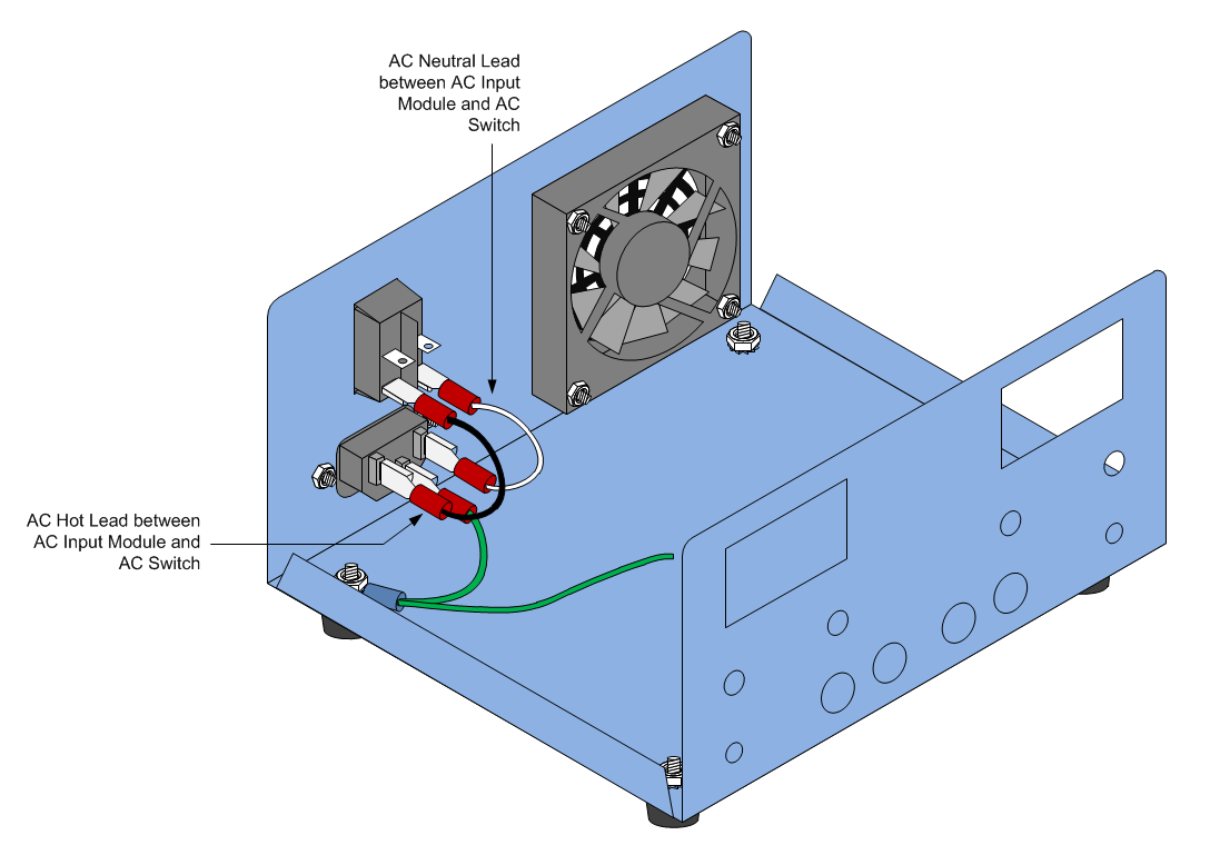
5. Connect one end of the black lead to the left lug of the AC input module. Connect the other end to the bottom left lug of the AC Power switch. Refer to the diagram below to verify that the black lead is connected properly.
6. Connect one end of the white lead to the right lug of the AC input module. Connect the other end to the bottom right lug of the AC Power switch. Refer to the diagram below to verify that the black lead is connected properly.
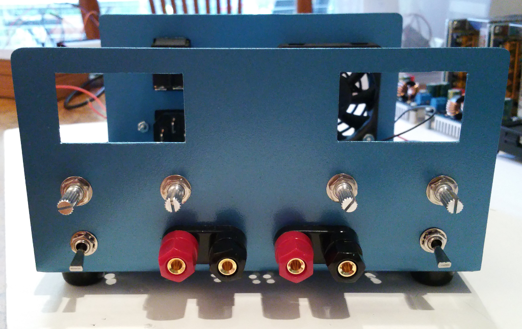
Install Front Panel Binding Posts
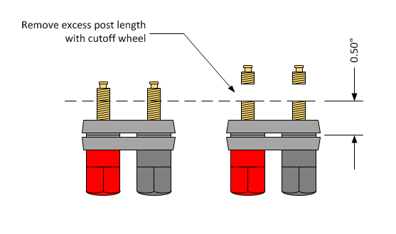
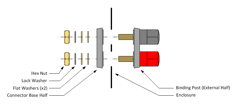
The binding posts from Vktech are ruggedly constructed and include a lot of mounting hardware which makes them a good value for the money. However the center conductors are about 1/2" longer than necessary which can waste a lot of space in the cabinet. To keep the supply compact, the binding posts must be modified as indicated in the above diagram and the following steps:
 1. Remove all the hardware from the binding post and pull off the rear plastic insulator.
2. Unscrew the Red and Black post caps several turns and push down firmly from the end each cap to make sure the center conductor is seated all the way down on the front plastic insulator.
3. Using a Sharpie pen and a ruler, measure and place a mark on the metal center conductors 1/2" from the front plastic insulator (refer to diagram above).
4. Using a cutoff wheel and a Dremel tool, cut through the metal center conductors at the marks to remove the top portion of the center conductors (refer to diagram above).
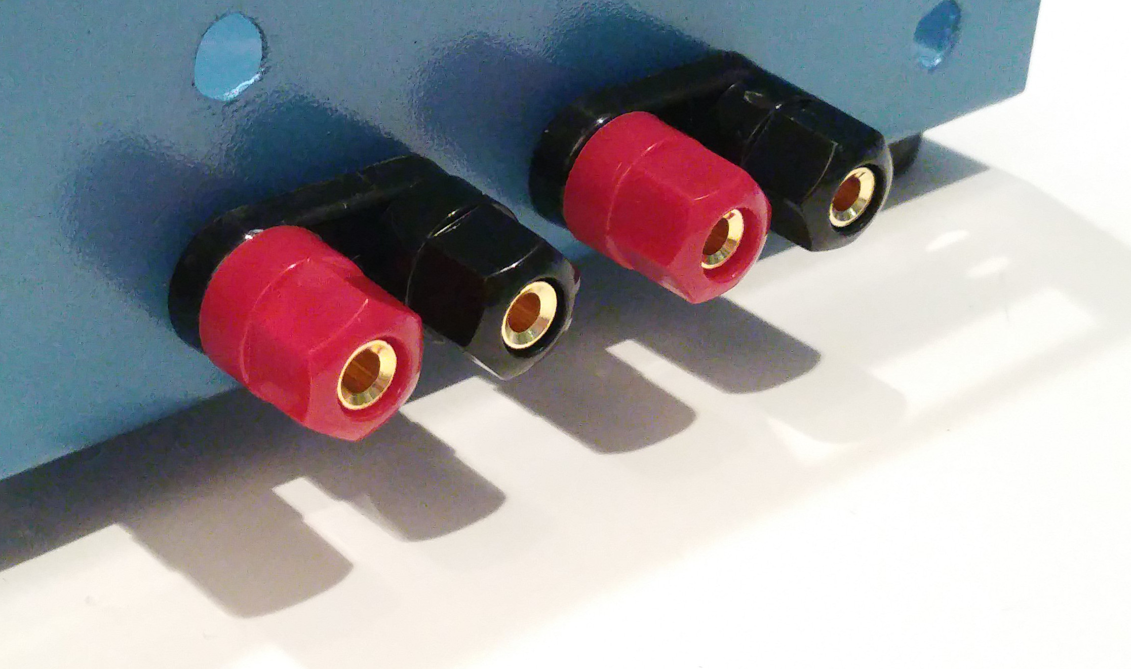
5. Insert the front portion of the binding post into the case (refer to above diagram).
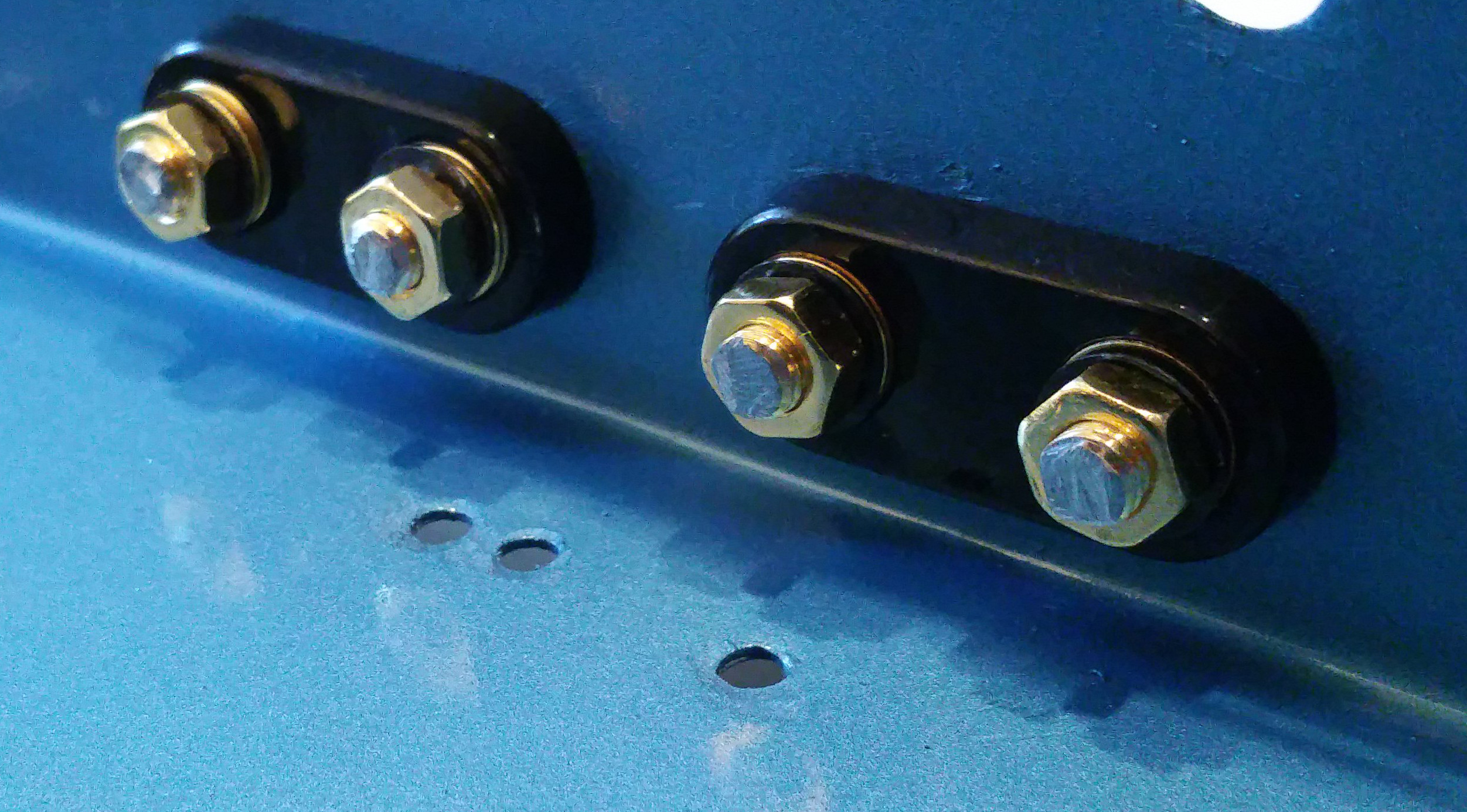
6. Slide on the rear plastic insulator, followed by two flat washers, and a lock washer on each center conductor (refer to above diagram). All hardware is included with the Vktech binding posts.
7. Thread a hex nut onto each binding post and hand tighten while sliding the insulators back and forth until they are seated properly in their holes. Do not tighten fully yet.
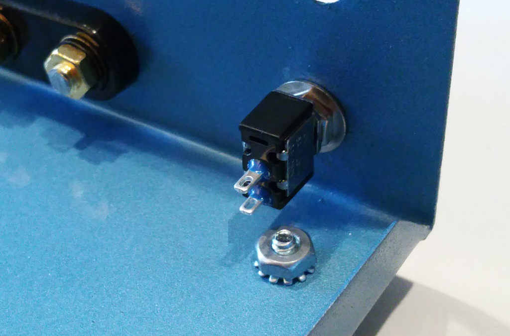
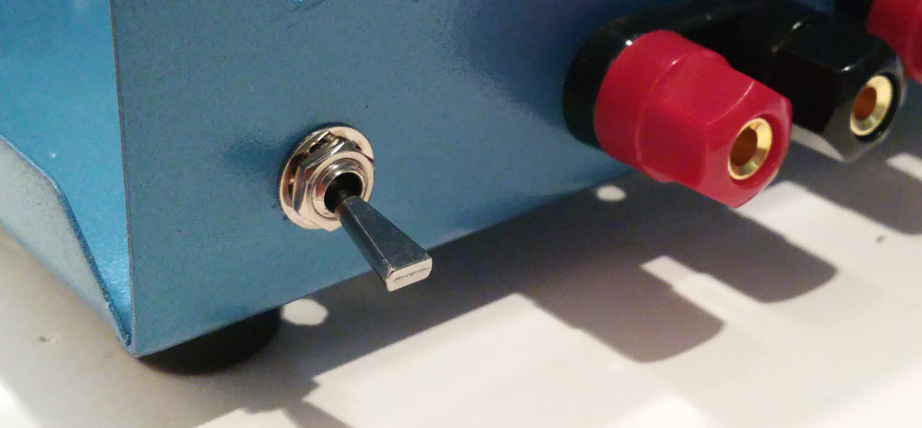
Install Front Panel Output Switches
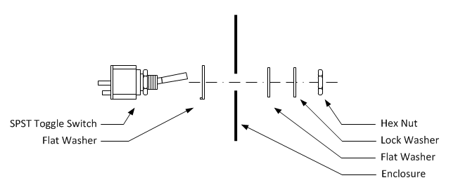
1. Remove the outer hex nut, lock washer, and flat washers from the SPST toggle switch.
2. Hand tighten the inner hex nut until snug against the switch body.
3. Install the large flat washer with the tab facing toward the switch body as illustrated in the diagram above.
4. Insert the SPST toggle switch into the bottom left hole in the front panel.
5. Orient the SPST toggle switch so that the two solder lugs are closest to the bottom of the enclosure as indicated in the diagram above.
6. Install the small flat washer onto the toggle barrel at the front of the enclosure as indicated in the diagram above.
7. Thread the hex nut onto the toggle barrel until hand tight.
8. Hold the switch body in position and firmly tighten the hex nut. The switch body should not move when the toggle switch is operated. If it does, tighten the hex nut until the switch body does not move.
Repeat the above for the SPST toggle switch on the bottom right of the front panel.
For reference, the SPST toggle switch datasheet is included >>> HERE <<<.
Install Potentiometers
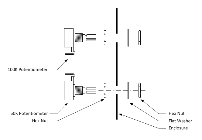
1. Thread a hex nut onto two 50K Ohm potentiometers and hand tighten until snug.
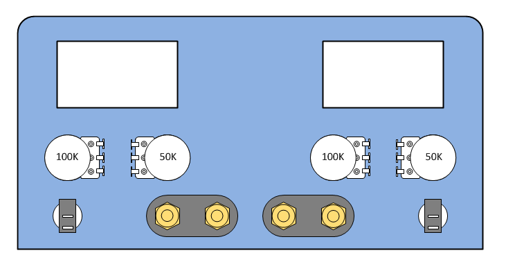
2. Insert the 50K Ohm potentiometers into the positions indicated in the above diagram.
3. Install a flat washer onto the 50K Ohm potentiometer shafts.
4. Thread a hex nut onto the 50K Ohm potentiometer shafts until hand tight.
5. Hold the potentiometer body in the position indicated in the above diagram and firmly tighten the hex nut. The potentiometer body should not move when the shaft is turned throughout it's full range of motion. If it does, tighten the hex nut until the potentiometer body does not move.
Repeat the above steps with the 100K Ohm potentiometers.
For reference, the potentiometer datasheet is included <<< HERE >>>.
Install V/I Meters
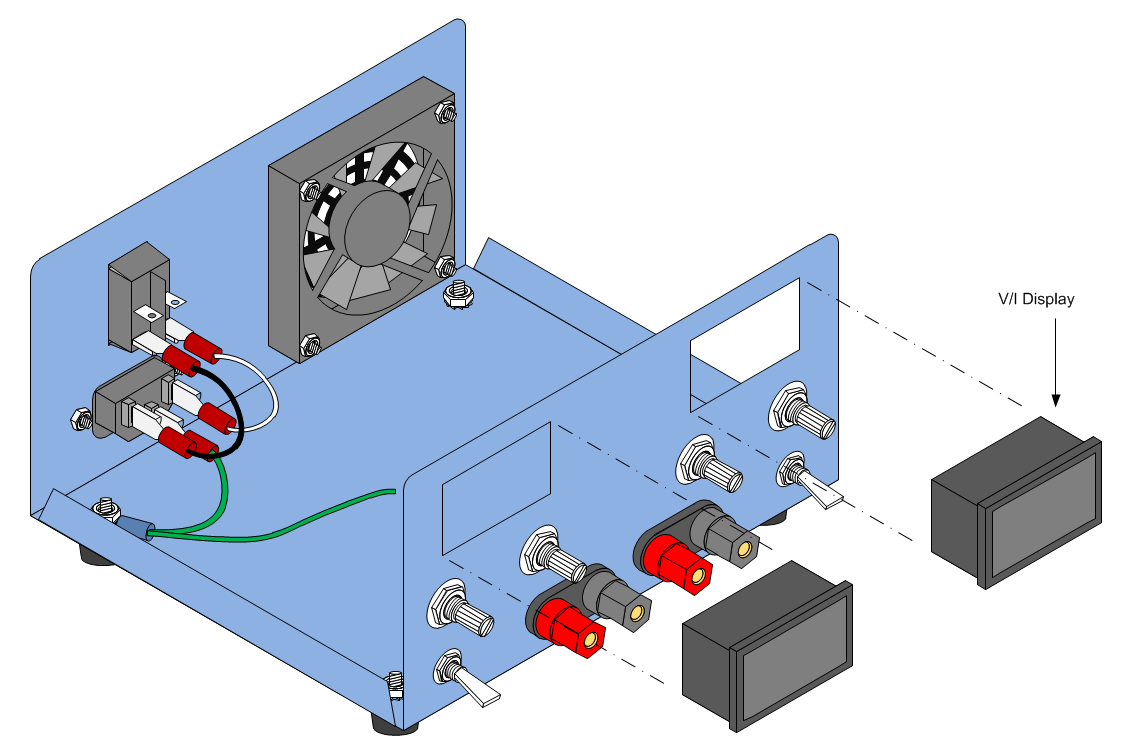
1. Insert the V/I displays half way into the cutouts provided.
2. Using fingertips or a screwdriver, depress the plastic retaining clips on the display bezel so that they clear the panel cutout.
3. While keeping the plastic retaining clips depressed, press the display into the cutout until the clips snap into place. Use care not to bend the panel while installing the displays.
Note: On some V/I displays the plastic retaining clips are too thick or too rigid to allow the display to be easily installed without bending the front panel. The best solution is to trim some of the plastic from the retaining clips until the display can be installed with reasonable force.
Note: On some displays the plastic retaining clips are too far back from the front bezel which causes the displays to fit loosely in the front panel. The best solution is to hold the display against the front panel while running a small bead of hot glue along the left and right side of the display (inside the case). Use caution to avoid getting glue on the outside front panel.
Install Control Knobs
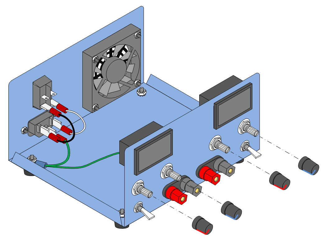
Insert the Red and Blue control knobs onto the front panel potentiometers as indicated in the above diagram.
The enclosure is now complete with all attachments and controls. The next section will describe how to install and wire the power supplies and converters.
For reference, the knob datasheet is attached >>> HERE <<<.
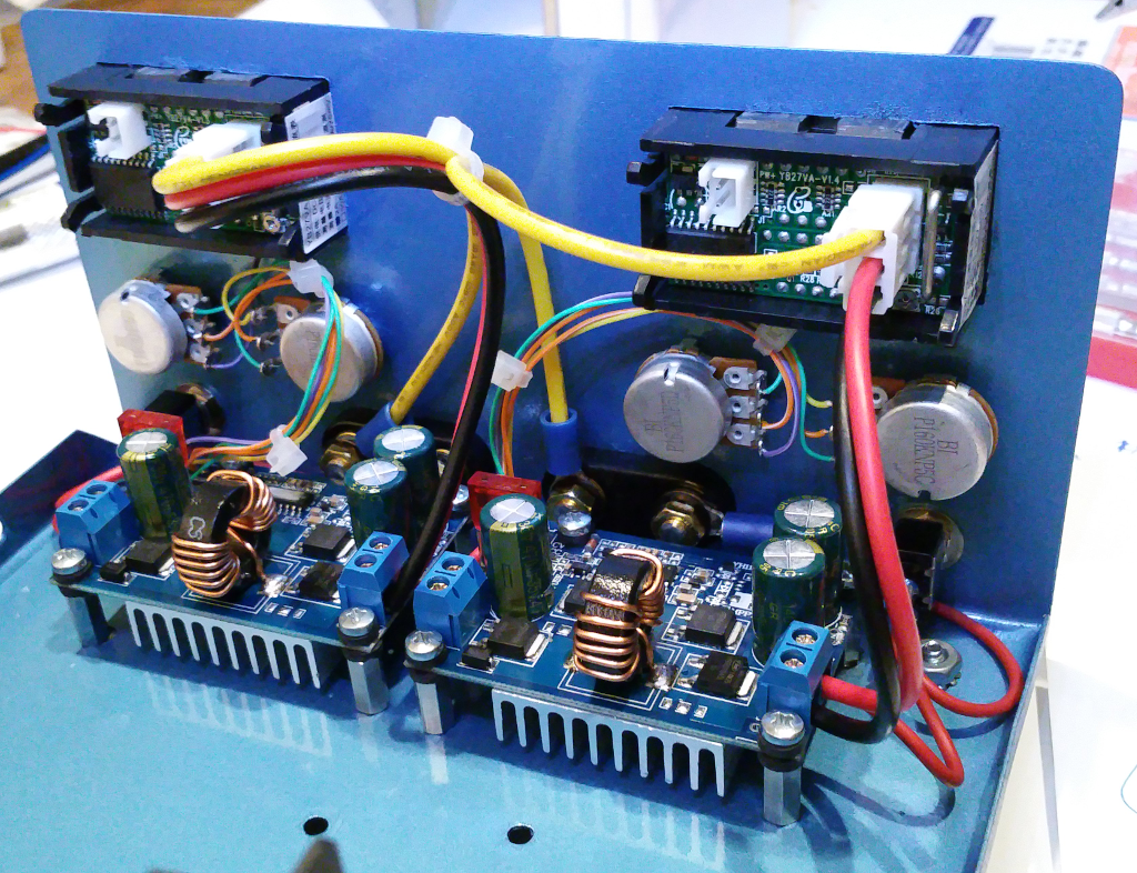
Prepare the DC-DC Converters
The DC-DC Converters used for this project accept a wide range of input voltages (5V - 32V) and convert that to a variable voltage between 1V and 20V with adjustable current limit between 0.1A and 3A. The DC-DC converters are operated in step-down switch-mode from a 24V DC input. The DROK converters are compact, easy to use, and >95% efficient for most of their range.
Adjustment of the output voltage and current limit is accomplished with two multi-turn trimmer resistors. In order to bring these adjustments to a potentiometer on the front panel, it is first necessary to remove the trimmer resistors. The quickest way to do that is to carefully cut them off of the board with a small pair of wire cutters. This might seem extreme but the PCB is very thick and the trimmer resistors are soft and easy to cut through. When the trimmer resistor body is removed, there will be three small component leads sticking up that can be easily desoldered. I believe this method is faster and results in less chance that pads and traces will be damaged from excess heat. I used the cut and release method on both converters with no problems. If you have a vacuum powered desoldering station by all means give that a try. Start with DC-DC Converter #1:
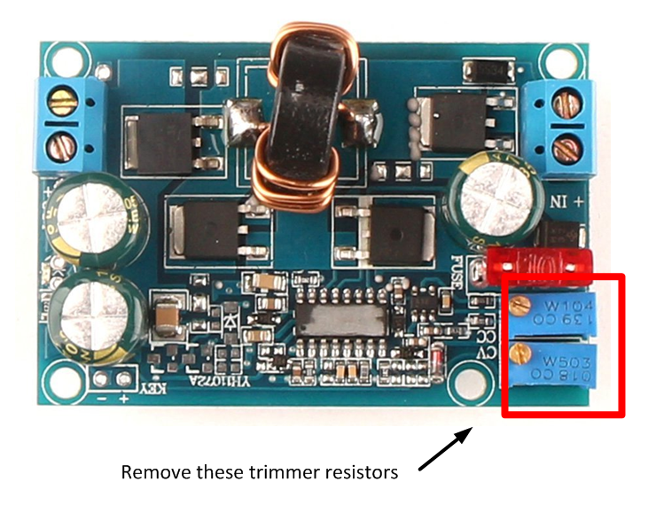
1. Notice that on each board the parameter that the trimmer resistor adjusts is indicated in white letters. On a blank piece of paper, draw an outline of the board and make a note of which trimmer is the voltage adjustment (CV) and which trimmer is the current adjustment (CC). On the DC-DC converters used for this project, the voltage trimmer was on the outside of the board and the current trimmer was next to the voltage trimmer.
2. Starting with the outside trimmer, use a small pair of wire cutters to cut a small groove into the outside corner of the trimmer body. Use one hand to hold onto the trimmer resistor while cutting with the other hand. Use only the force necessary to keep the wire cutter blades in contact with the trimmer body. Let the scissor action of the wire cutters do the work. The goal is to cut through the plastic body of the trimmer. Don't try to cut too much at one time.
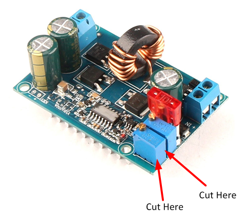
3. When the corner gap is deep enough, begin cutting a groove into the adjacent corner next to the inside trimmer. When the second groove is deep enough, cut through the side of the trimmer body. There may be a crunching sound as the wire cutters reach internal ceramic components. Do not be concerned. Only the trimmer is being damaged.
4. Starting with the opposite outside corner of the trimmer, begin cutting a groove into the trimmer body.

5. When the groove is deep enough, cut through the short side of the trimmer body. Don't attempt to cut through the metal adjustment screw.
6. At this point, the trimmer body will crack and separate in half. Remove the ceramic disk and brass adjustment hardware.
7. Using needle nose pliers, straighten the three wires sticking up from the remains of the trimmer body.
8. Carefully cut away the remaining bottom of the trimmer body leaving only the three wires sticking up from the PCB. Do not cut these wires as the remaining length will aid in removing the wires from the PCB.
9. Repeat steps 2 through 8 for the remaining trimmer resistor.
10. Desolder the trimmer wires and clear as much as solder as possible from the pad holes.
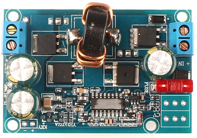
By working carefully and slowly, it is easy to remove the trimmer resistors without harming nearby components or the PCB.
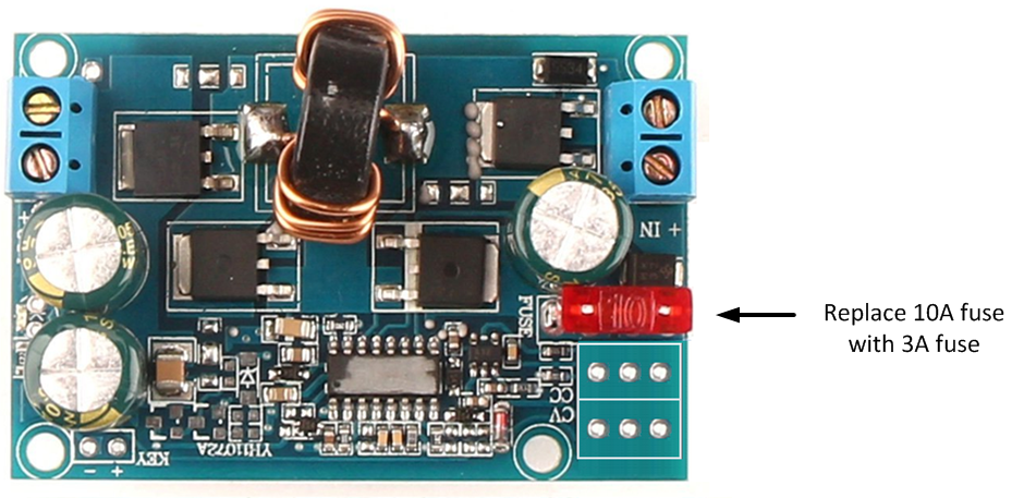
11. Remove the 10A output fuse and replace with a 3A fuse.
12. Cut 4" lengths of #28 or smaller stranded hookup wire. Choose wire with different color jackets to make identification easier when the wires are soldered to the potentiometers in a later step.
13. Strip 1/4" insulation from both ends of each wire and tin the ends with solder.
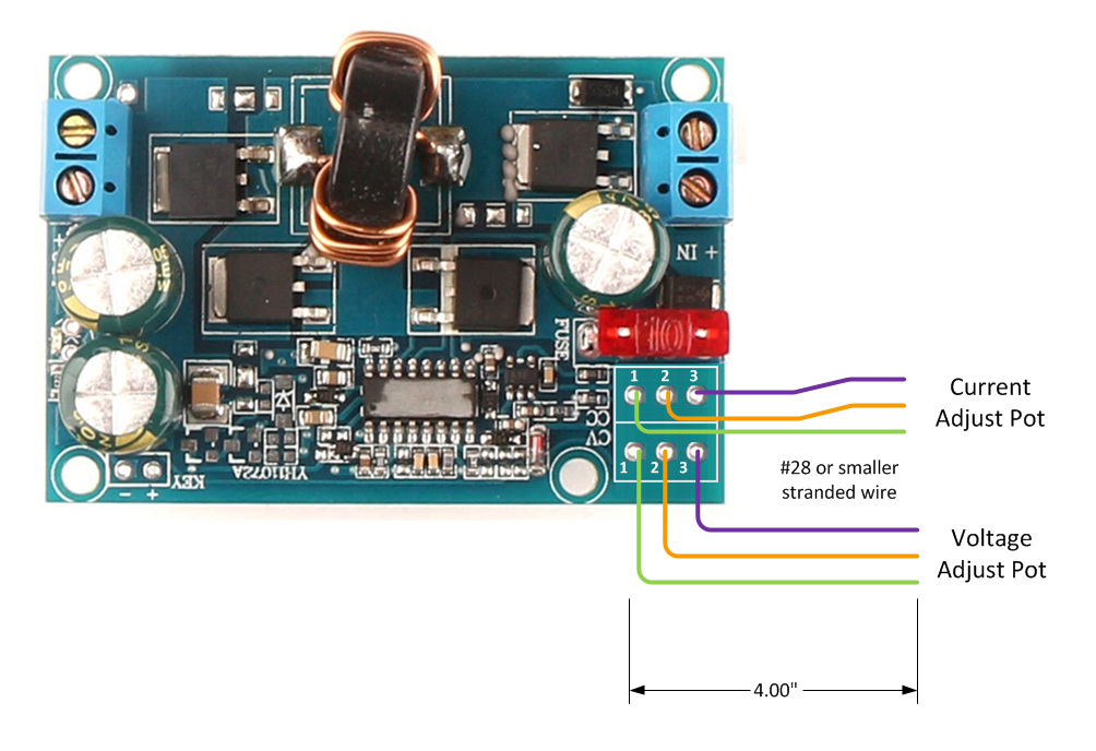
14. Solder each wire to the DC-DC converter solder pads as illustrated above.
Repeat the above steps for DC-DC Converter #2.
Note: In the illustration above the potentiometer pads are labeled 1, 2, and 3. These numbers (and wire colors) will be referred to when soldering the converter leads to the potentiometers. The jacket color chosen in this step is arbitrary. Any color can be used as long as the builder remembers to match the instructable colors with the actual colors so that the potentiometer leads are soldered to the correct pin.
Attach Enclosure Standoffs Using Screws and Insulating Washers
The IAASR SimCase product comes with 9 standoffs and 18 machine screws that work perfectly with the DROK DC-DC converters. Remove these standoffs from the case for use with mounting the converters.
If using a different enclosure, the converters will require eight #8 hex standoffs and 16 #8 machine screws.
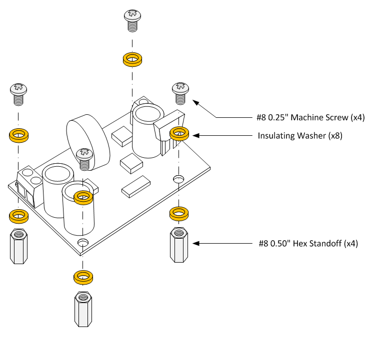
Insulating washers are used ensure no exposed traces on the DC-DC converters come in contact with the enclosure and AC safety ground. They also add some height to the standoffs so that there is enough clearance for the PCB heat sink.
1. Insert one insulating washer on a #8 machine screw.
Note: The washer may be a tight fit on some screws. If the washer cannot be easily installed on the machine screw, increase the diameter of the washer slightly with a push drill.
2. Insert the machine screw and washer into a mounting hole on DC-DC converter #1.
3. Insert one insulating washer onto the screw where it exits the opposite side of the PCB.
4. Thread the hex standoff onto the screw until hand tight.
5. While holding the standoff with a pair of pliers or adjustable wrench, firmly tighten the screw.
6. Repeat steps 1 through 5 for the remaining PCB mounting holes.
Repeat the above for the DC-DC Converter #2.
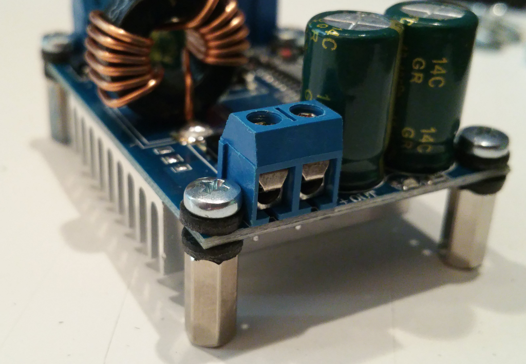
Install DC-DC Converters
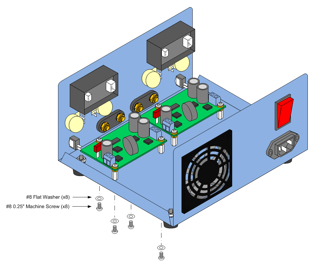
1. Line up the holes in the front of the enclosure with the hex standoffs of DC-DC Converter #1.
2. Insert a #8 flat washer onto a #8 0.5" machine screw.
3. Tread the machine screw through the bottom of the enclosure and into the hex standoff.
4. Hand tighten the machine screw.
5. Repeat steps 2 through 4 for each remaining hex standoff.
6. When all 4 machine screws and flat washers are installed, firmly tighten each screw.
7. Repeat steps 1 through 6 for DC-DC converter #2.
Build Front Panel Cables
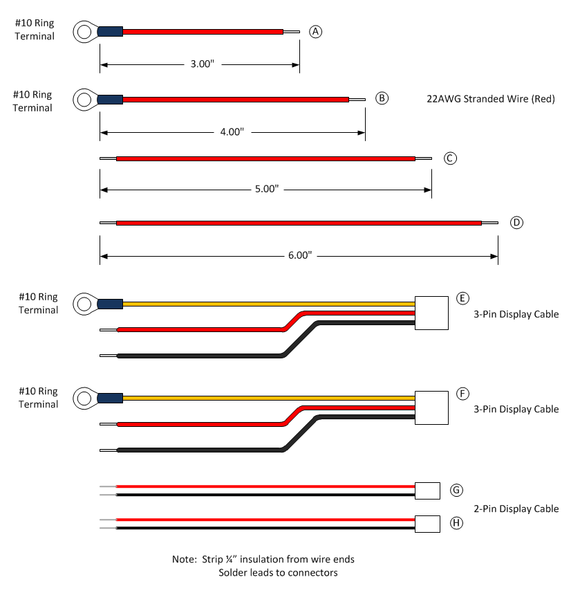
1. Cut a piece of 22AWG stranded red wire 4" long. Strip 1/4" insulation from each end and tin with solder.
2. Solder a #10 Ring Connector on one end of the 4" wire wire.
3. Cut a piece of 22AWG stranded red wire 3" long. Strip 1/4" insulation from each end and tin with solder.
4. Solder a #10 Ring Connector on one end of the 3" wire.
5. Cut a piece of 22AWG stranded red wire 5" long. Strip 1/4" insulation from each end and tin with solder.
6. Cut a piece of 22AWG stranded red wire 6" long. Strip 1/4" insulation from each end and tin with solder.
7. Strip 1/4" insulation from each lead attached to the 3-pin display connector and tin with solder.
8. Solder a #10 Ring connector to both Yellow leads attached to the 3-pin display connector.
9. Strip 1/4" insulation from each lead attached to the 2-pin display connector and tin with solder.
Wire the Front Panel Power Connections
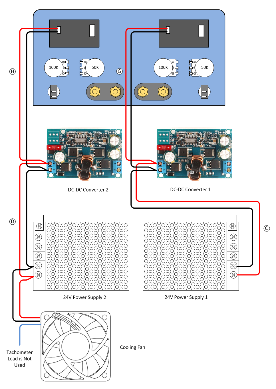
Use the diagram above in parallel with the following instructions to complete the output power connections on the front panel.
1. Remove the hex bolt and lock washer from the positive (Red) Power Supply 1 binding post.
2. Install the Ring Terminal of Cable A followed by the lock washer onto the positive (Red) Power Supply 1 binding post.
3. Thread the hex bolt onto the positive (Red) Power Supply 1 binding post and tighten firmly. Do not over-tighten the hex bolt.
4. Solder the free end of Cable A onto the lower pin of the Power Supply 1 SPST power switch.
5. Remove the hex bolt and lock washer from the positive (Red) Power Supply 2 binding post.
6. Install the Ring Terminal of Cable B followed by the lock washer onto the positive (Red) Power Supply 2 binding post.
7. Thread the hex bolt onto the positive (Red) Power Supply 2 binding post and tighten firmly. Do not over-tighten the hex bolt.
8. Solder the free end of Cable B onto the lower pin of the Power Supply 2 SPST power switch.
9. Solder one end of Cable C to the upper pin of the Power Supply 1 SPST power switch. Route the other end of Cable C to the output connector of DC-DC Converter 1 but do not attach yet.
10. Solder one end of Cable D to the upper pin of the Power Supply 2 SPST power switch. Route the other end of Cable D to the output connector of DC-DC Converter 2 but do not attach yet.
11. Remove the hex bolt and lock washer from the negative (Black) Power Supply 1 binding post.
12. Install the Ring Terminal of Cable E followed by the lock washer onto the negative (Black) Power Supply 1 binding post.
13. Thread the hex bolt onto the negative (Black) Power Supply 1 binding post and tighten firmly. Do not over-tighten the hex bolt.
14. Remove the hex bolt and lock washer from the negative (Black) Power Supply 2 binding post.
15. Install the Ring Terminal of Cable F followed by the lock washer onto the negative (Black) Power Supply 2 binding post.
16. Thread the hex bolt onto the negative (Black) Power Supply 2 binding post and tighten firmly. Do not over-tighten the hex bolt.
17. Plug the 3-pin connector of Cable E onto Power Supply 1 display module.
18. Plug the 3-pin connector of Cable F onto Power Supply 2 display module.
19. Insert the Red wire from Cable E and the Red wire Cable C into the DC-DC Converter 1 output terminal block positive (+) position and firmly tighten the terminal block screw. Do not over-tighten the terminal block screw.
20. Insert the Black wire from Cable E into the DC-DC Converter 1 output terminal block negative (-) position and firmly tighten the terminal block screw. Do not over-tighten the terminal block screw.
21. Insert the Red wire from Cable F and the Red wire Cable D into the DC-DC Converter 2 output terminal block positive (+) position and firmly tighten the terminal block screw. Do not over-tighten the terminal block screw.
22. Insert the Black wire from Cable F into the DC-DC Converter 2 output terminal block negative (-) position and firmly tighten the terminal block screw. Do not over-tighten the terminal block screw.
Wire the Front Panel Potentiometers
Use the diagrams below in parallel with the following instructions to complete the potentiometer connections on the front panel.
1. Solder the CV leads from DC-DC Converter 1 to the 50K voltage adjust potentiometer. Solder pins 1 through 3 on the DC-DC Converter PCB to pins 1 through 3 on the potentiometer as illustrated below.
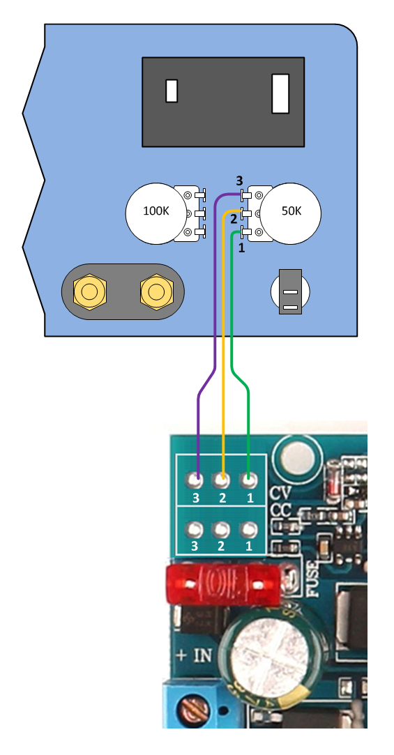
2. Solder the CC leads from DC-DC Converter 1 to the 100K current adjust potentiometer. Solder pins 1 through 3 on the DC-DC Converter PCB to pins 1 through 3 on the potentiometer as illustrated below.
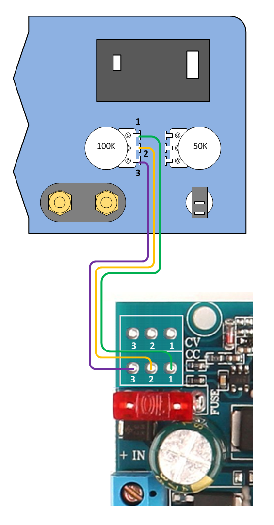
3. Solder the CV leads from DC-DC Converter 2 to the 50K voltage adjust potentiometer. Solder pins 1 through 3 on the DC-DC Converter PCB to pins 1 through 3 on the potentiometer as illustrated below.
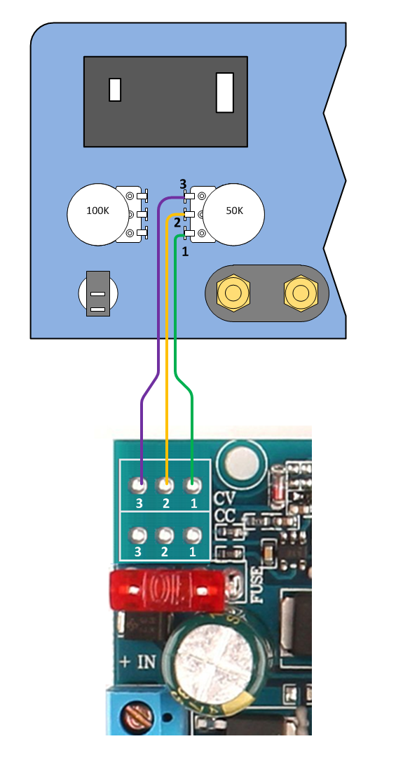
4. Solder the CC leads from DC-DC Converter 2 to the 100K current adjust potentiometer. Solder pins 1 through 3 on the DC-DC Converter PCB to pins 1 through 3 on the potentiometer as illustrated below.

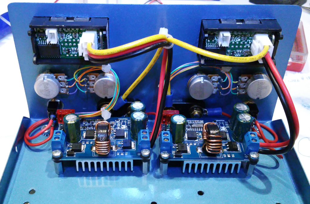
Dress Front Panel Wiring With Plastic Cable Ties
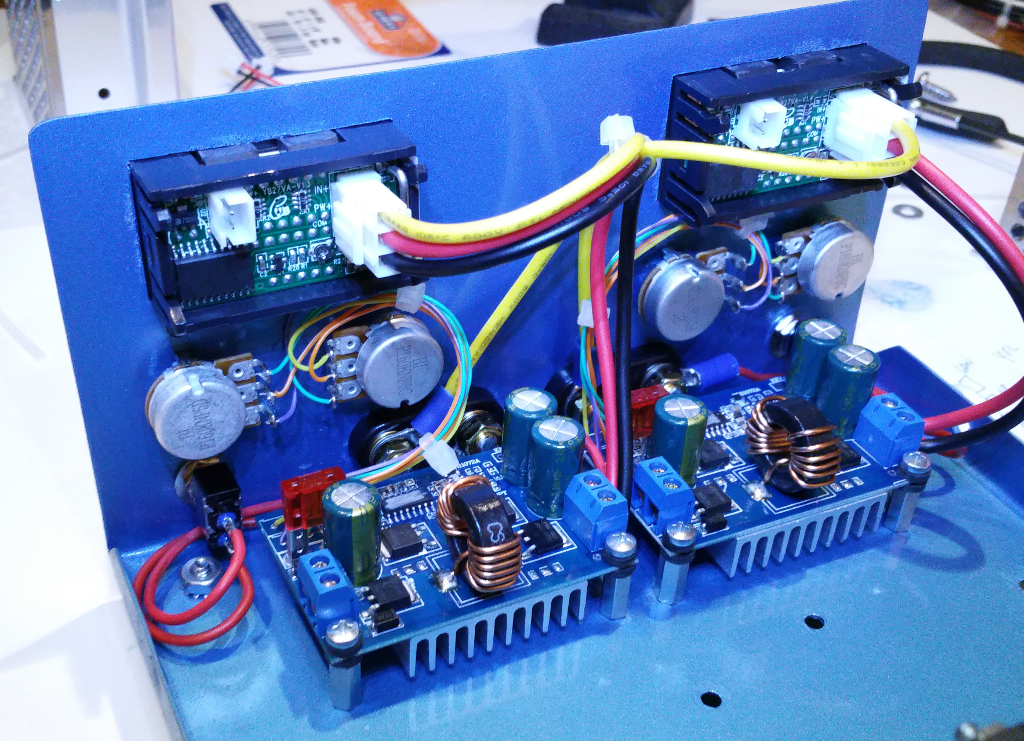
Double-check front panel wiring. Using small plastic cable ties, dress the front panel cabling for appearance.
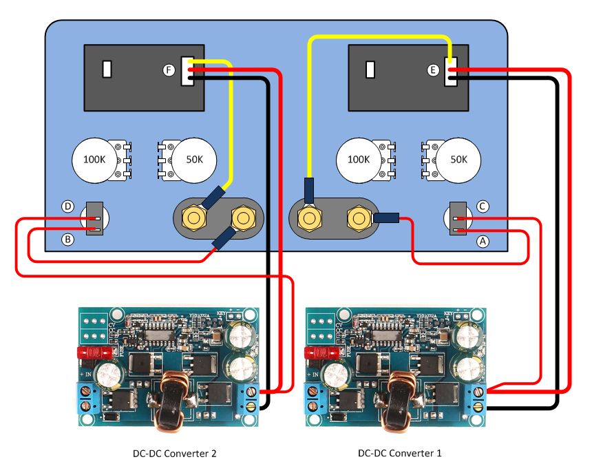
Wire the 24V Power Supplies
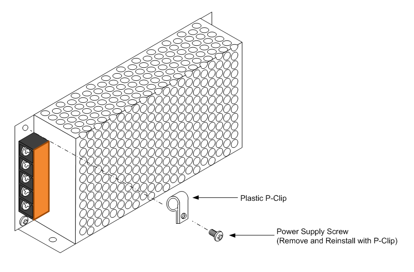
1. Remove one screw above the barrier strip from each 24V power supply as indicated in the above illustration.
2. Install a plastic P-Clip using the screw just removed oriented as indicated in the above diagram.
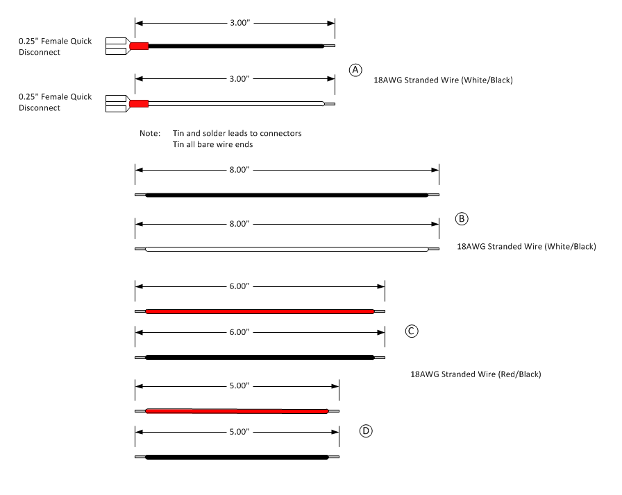
3. Build cables A, B, C, and D as indicated in the diagram above. Strip 1/4" insulation from both ends of each wire. Solder all connectors and tin all bare wire ends.
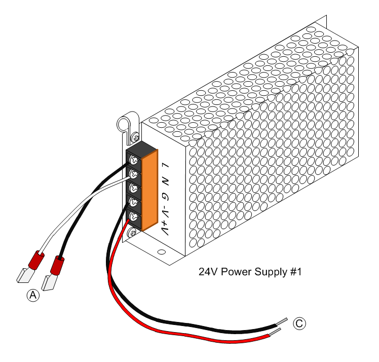
4. Attach cables A and C to 24V Power Supply 1 as indicated in the above illustration. The Black wire of cable A connects to the barrier screw marked 'L'. The White wire of cable A connects to the barrier screw marked 'N'. The Black wire of cable C connects to the barrier screw marked '-V'. The Red wire of cable C connects to the barrier screw marked '+V'.
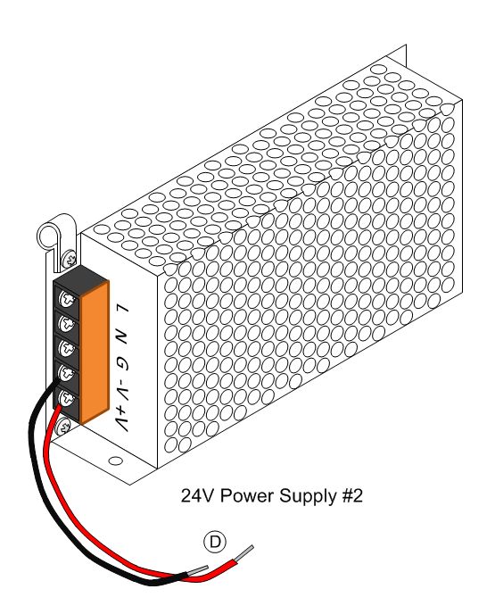
5. Attach cable D to 24V Power Supply 2 as indicated in the above illustration. The Black wire of cable D connects to the barrier screw marked '-V'. The Red wire of cable D connects to the barrier screw marked '+V'.
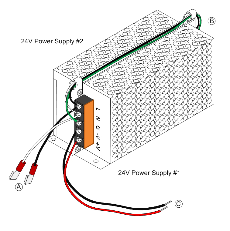
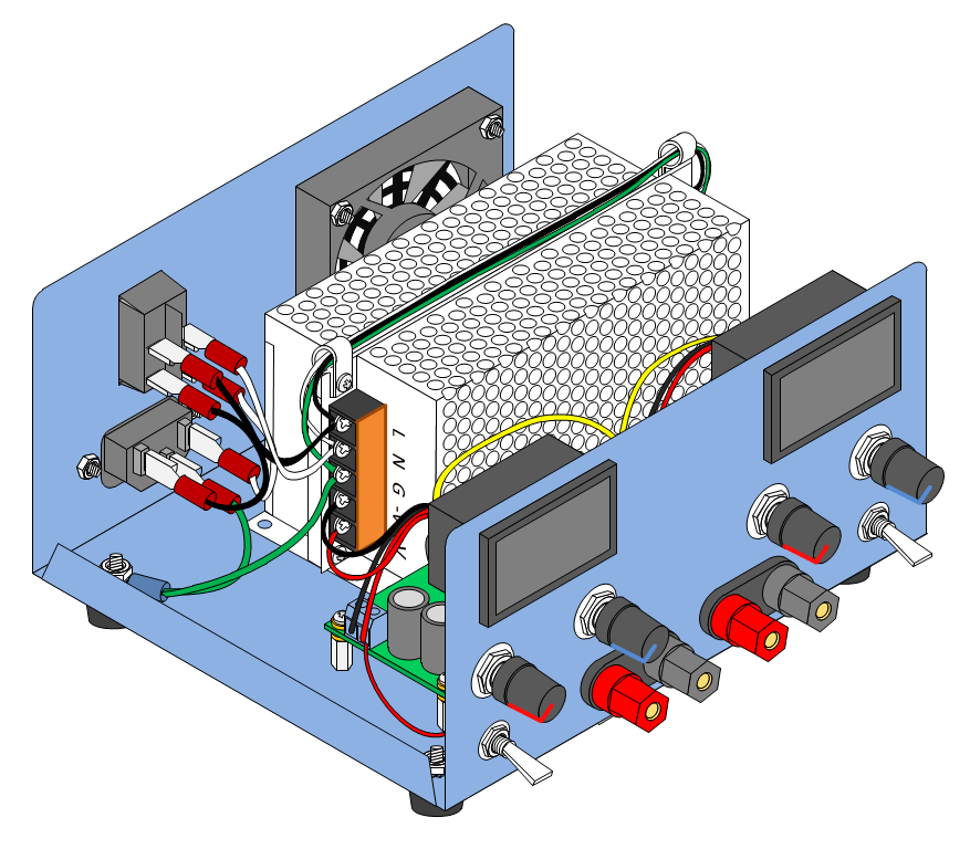
6. Place 24V Power Supply 1 and 2 back to back as illustrated in the diagram above.
7. Connect cable B between 24V Power Supply 1 and 2 by threading the wire through the P-Clips. The Black wire of cable B connects to the barrier screw marked 'L' on both supplies. The White wire of cable B connects to the barrier screw marked 'N' on both supplies. The Green wire of cable B connects to the barrier screw marked 'G' on both supplies.
Install the 24V Power Supplies
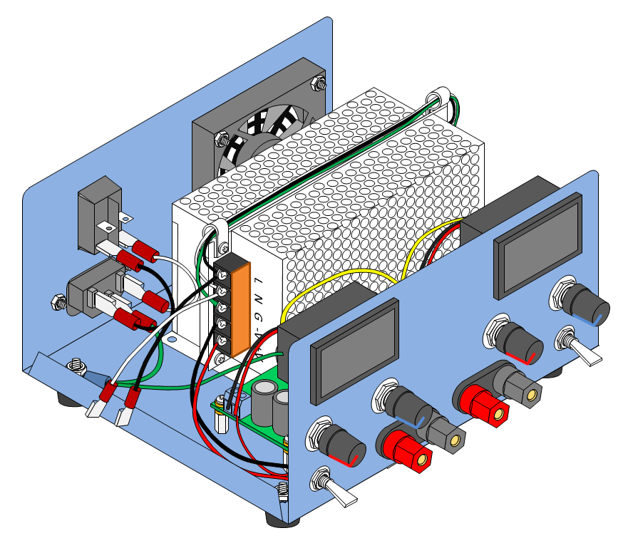
Lift both 24V Power Supplies and place them in the enclosure as indicated in the diagram above. Verify that the power supply modules align with the enclosure mounting holes but do not fasten the power supplies at this time.
Complete Wiring of the 24V Power Supplies
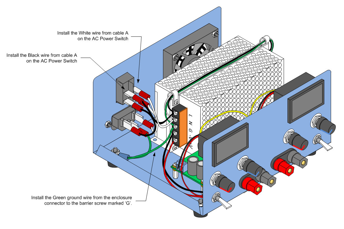
1. Attach the 24V Power Supply AC input and ground leads as indicated in the diagram above above.
2. Plug the 2-Pin connectors G and H into the V/I displays.
3. Connect cable C from 24V Power Supply 1 to DC-DC Converter 1. The Red wire connects to the 'IN+' screw terminal of the DC-DC Converter as shown in the diagram above. The Black wire connects to the 'IN-' screw terminal of the DC-DC Converter as shown in the diagram above.
4. Connect 2-Pin cable G to DC-DC Converter 1. The Red wire connects to the 'IN+' screw terminal of the DC-DC Converter as shown in the diagram above. The Black wire connects to the 'IN-' screw terminal of the DC-DC Converter as shown in the diagram above.
5. Connect cable D from 24V Power Supply 2 to DC-DC Converter 2. The Red wire connects to the 'IN+' screw terminal of the DC-DC Converter as shown in the diagram above. The Black wire connects to the 'IN-' screw terminal of the DC-DC Converter as shown in the diagram above.
6. Connect 2-Pin cable H to DC-DC Converter 2. The Red wire connects to the 'IN+' screw terminal of the DC-DC Converter as shown in the diagram above. The Black wire connects to the 'IN-' screw terminal of the DC-DC Converter as shown in the diagram above.
7. Connect the Cooling Fan cable to 24V Power Supply 2 as shown in the diagram above. The Red wire connects to the barrier screw marked '+V' on 24V Power Supply 2. The Black wire connects to the '-V' barrier screw on 24V Power Supply 2. The Cooling Fan Blue tachometer wire is not used.
8. Secure the 24V power supplies to the enclosure with four #8 machine screws, washers, and lock nuts.
9. Dress all wires and secure with cable ties.
Testing Before Power-On
Before plugging in and powering on the completed power supply for the first time, perform the following checks:
1. Using a digital VOM set to Ohms, measure the resistance between the 'L' and 'N' binding screws on 24V Power Supply 1. The VOM should read very high (>10K Ohms) or infinite resistance. If the VOM reads low resistance or a short circuit, verify that all AC wiring is correct using the power supply schematic diagram. DO NOT CONNECT THE POWER SUPPLY TO AN AC OUTLET UNTIL THE MEASUREMENT IS CORRECT (VERY HIGH OR INFINITE RESISTANCE).
2. Using a digital VOM set to OHMS, measure the resistance between the 'L' and 'G' binding screws on 24V Power Supply 1. The VOM should read very high (>10K Ohms) or infinite resistance. If the VOM reads low resistance or a short circuit, verify that all AC wiring is correct using the power supply schematic diagram. DO NOT CONNECT THE POWER SUPPLY TO AN AC OUTLET UNTIL THE MEASUREMENT IS CORRECT (VERY HIGH OR INFINITE RESISTANCE).
3. Using a digital VOM set to OHMS, measure the resistance between the 'N' and 'G' binding screws on 24V Power Supply 1. The VOM should read very high (>10K Ohms) or infinite resistance. If the VOM reads low resistance or a short circuit, verify that all AC wiring is correct using the power supply schematic diagram. DO NOT CONNECT THE POWER SUPPLY TO AN AC OUTLET UNTIL THE MEASUREMENT IS CORRECT (VERY HIGH OR INFINITE RESISTANCE).
If any of the above measurements are not correct and all wiring has been verified, do not proceed and do not connect the power supply to an AC outlet. Contact the 24V AC Power Supply representative for further instructions.
4. Make sure the power supply output SPST switches are in the OFF (Down) position.
5. Using a digital VOM set to OHMS, measure the resistance between the Positive (Red) output binding post and the Negative (Black) output binding post of power supply 1 (Left Side). The VOM should read very high (>10K Ohms) or infinite resistance. If the VOM reads low resistance or a short circuit, verify that all DC-DC Converter output wiring is correct using the power supply schematic diagram. Check that the output binding post is properly seated in the front panel and that there are no bits of wire or solder touching the power supply enclosure or other circuit connections. Do not proceed until the resistance is within the indicated range (>10K Ohms).
6. Using a digital VOM set to OHMS, measure the resistance between the Positive (Red) output binding post and the Negative (Black) output binding post of power supply 2 (Right Side) . The VOM should read very high (>10K Ohms) or infinite resistance. If the VOM reads low resistance or a short circuit, verify that all DC-DC Converter output wiring is correct using the power supply schematic diagram. Check that the output binding post is properly seated in the front panel and that there are no bits of wire or solder touching the power supply enclosure or other circuit connections. Do not proceed until the resistance is within the indicated range (>10K Ohms).
7. Put both power supply output SPST switches in the ON (Up) position.
8. Using a digital VOM set to OHMS, measure the resistance between the Positive (Red) output binding post and the Negative (Black) output binding post of power supply 1 (Left Side). The VOM should read very high (>10K Ohms) or infinite resistance. If the VOM reads low resistance or a short circuit, verify that all DC-DC Converter output wiring is correct using the power supply schematic diagram. If after verifying that circuit wiring is correct, do not proceed. Contact the DC-DC Converter representative for further instructions.
9. Using a digital VOM set to OHMS, measure the resistance between the Positive (Red) output binding post and the Negative (Black) output binding post of power supply 2 (Right Side). The VOM should read very high (>10K Ohms) or infinite resistance. If the VOM reads low resistance or a short circuit, verify that all DC-DC Converter output wiring is correct using the power supply schematic diagram. If after verifying that circuit wiring is correct, do not proceed. Contact the DC-DC Converter representative for further instructions.
10. Attach a power cord to the power supply AC Input Module. DO NOT PLUG THE POWER CORD INTO AN AC OUTLET.
11. Turn on the AC Power Switch.
12. Using a digital VOM set to OHMS, measure the resistance between the power cord hot and neutral conductors. The VOM should read very high (>10K Ohms) or infinite resistance. If the VOM reads low resistance or a short circuit, verify that all AC wiring between the AC Input Module and the AC Power Switch is correct using the power supply schematic diagram. DO NOT CONNECT THE POWER SUPPLY TO AN AC OUTLET UNTIL THE MEASUREMENT IS CORRECT (VERY HIGH OR INFINITE RESISTANCE).
13. Using a digital VOM set to OHMS, measure the resistance between the power cord hot and ground conductors. The VOM should read very high (>10K Ohms) or infinite resistance. If the VOM reads low resistance or a short circuit, verify that all AC wiring between the AC Input Module and the AC Power Switch is correct using the power supply schematic diagram. DO NOT CONNECT THE POWER SUPPLY TO AN AC OUTLET UNTIL THE MEASUREMENT IS CORRECT (VERY HIGH OR INFINITE RESISTANCE).
14. Using a digital VOM set to OHMS, measure the resistance between the power cord neutral and ground conductors. The VOM should read very high (>10K Ohms) or infinite resistance. If the VOM reads low resistance or a short circuit, verify that all AC wiring between the AC Input Module and the AC Power Switch is correct using the power supply schematic diagram. DO NOT CONNECT THE POWER SUPPLY TO AN AC OUTLET UNTIL THE MEASUREMENT IS CORRECT (VERY HIGH OR INFINITE RESISTANCE).
Attach the Top Cover
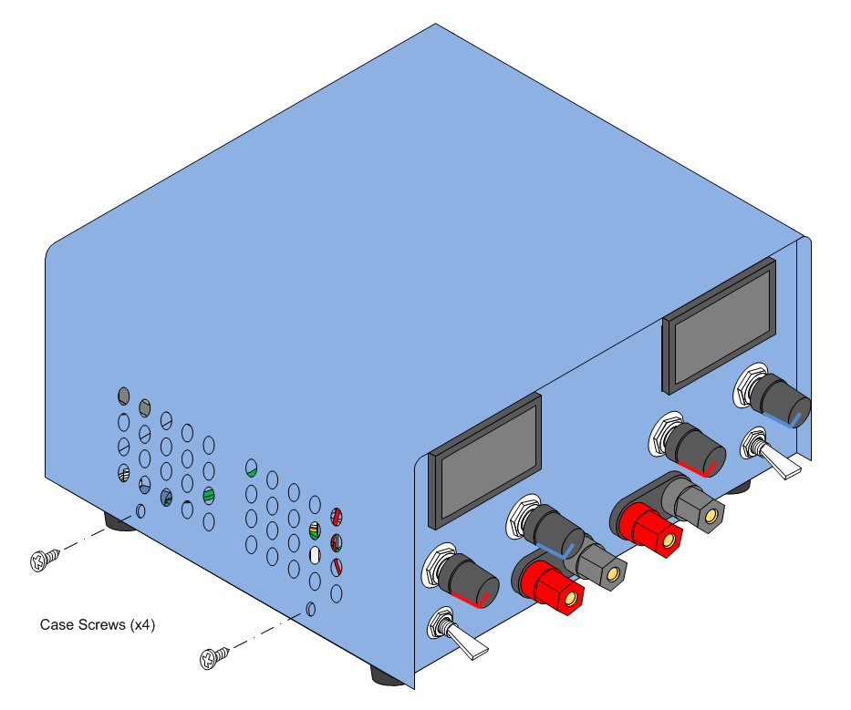
Place the enclosure top over the power supply chassis and line up the holes in the top cover with the holes in the base. Secure the top to the base with the screws supplied by the enclosure vendor.
Power-On Testing
1. Verify that the back panel AC Power Switch is in the Off position.
2. Verify that the front panel Output SPST switches are in the Off (Down) position.
3. Verify that the front panel Voltage and Current controls are rotated fully counter clockwise.
3. Plug the power supply power cord into an AC outlet.
4. Turn on the AC Power Switch
The AC Power Switch will illuminate. If it does not illuminate, verify that the AC Outlet is energized and that the power cord is fully plugged into the outlets at both ends. IF THE AC POWER SWITCH DOES NOT ILLUMINATE, REMOVE THE POWER CORD FROM THE AC OUTLET.
5. The Cooling Fan will turn on and the front panel V/I displays will illuminate. If the cooling fan or V/I displays do not come on, turn off the AC power switch and disconnect the power cord from the AC outlet. Remove the top cover and verify that the fan or display wiring is correct. If the fan or display wiring is correct, contact the fan or display representative for further instructions.
6. The front panel V/I displays should indicate approximately 1.00V and 1.50V for the output voltage and 0.00A for the output current. If the V/I display indicates approximately 20V with the voltage controls fully counter-clockwise, turn off the AC power switch and disconnect the power cord from the AC outlet. Remove the top cover and verify that the voltage potentiometer wiring is correct. If the potentiometer wiring is correct, contact the DC-DC Converter representative for further instructions.
7. Rotate the Power Supply 1 (Left Side) voltage control clockwise. The V/I display should show the output voltage increasing as the control is turned clockwise and decreasing when the control is turned counter-clockwise. If the V/I display does not change in value as the voltage control is rotated, turn off the AC power switch and disconnect the power cord from the AC outlet. Remove the top cover and verify that the voltage potentiometer wiring is correct. If the potentiometer wiring is correct, contact the DC-DC Converter representative for further instructions.
8. Rotate the Power Supply 2 (Right Side) voltage control clockwise. The V/I display should show the output voltage increasing as the control is turned clockwise and decreasing when the control is turned counter-clockwise. If the V/I display does not change in value as the voltage control is rotated, turn off the AC power switch and disconnect the power cord from the AC outlet. Remove the top cover and verify that the voltage potentiometer wiring is correct. If the potentiometer wiring is correct, contact the DC-DC Converter representative for further instructions.
Optional Load Testing
9. Rotate all front panel voltage and current controls fully counter clockwise.
10. Verify that both output SPST switches are in the Off (Down) position.
10. Attach a 10 Ohm, 20W resistor between the Positive (Red) and Negative (Black) output binding posts of Power Supply 1 (Left Side).
11. Flip the Power Supply 1 output SPST switch to the ON position.
12. The V/I display should show an output current of approximately 0.10A
13. Flip the Power Supply 1 output SPST switch to the OFF position.
14. Rotate the voltage control until the V/I display reads 10V.
15. Flip the Power Supply 1 output SPST switch to the ON position.
16. The V/I display should indicate a reduced output voltage and between 0.10A and 0.20A.
17. Slowly rotate the current control until the V/I display reads 10V and approximately 1.00A.
18. Flip the Power Supply 1 output SPST power switch to the OFF position.
19. Remove the 10 Ohm, 20W resistor from the output binding post of Power Supply 1.
20. Attach a 10 Ohm, 20W resistor between the Positive (Red) and Negative (Black) output binding posts of Power Supply 2 (Right Side).
21. Repeat steps 11 through 19 for Power Supply 2.
22. Turn off the AC Power Switch and disconnect the AC Power Cord from the AC wall outlet.
The Dual Switched-Mode Power Supply is ready for use.