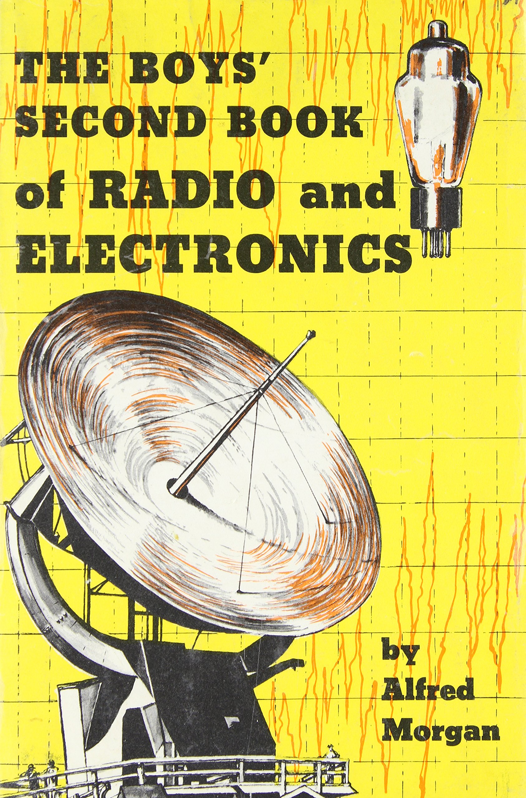
I've been fascinated with the early history of radio and television between 1870 through 1929 since reading a very old copy of "The Boys Second Book of Radio and Electronics" by Alfred Morgan, found in the dusty science shelves of my highschool library (I'm a "geek" and that book made me happy). This period is dominated by some very interesting and bizarre personalities like Thomas Edison, Guglielmo Marconi, John Fleming, Nikola Tesla, Reginald Fessenden, Lee de Forest, and Edwin Armstrong. These people are credited with the fundamental inventions commercialized by RCA, GE, AT&T, and Westinghouse; companies which flourished in the golden age of radio and still exist today!
They were mostly experimenters and tinkerers at a time when academic research was often unconcerned with the practical application of a scientific discovery. As a result the industry did not have a good understanding of how the electronic devices they were building actually worked. At times the money to be made from broadcast radio, the competitive litigation that inevitably follows the profits, and the government regulation intended to control on overheated emerging industry became more significant than the technology. Kind of like it does today, right? These are the major reasons why there isn't a Wright Brothers airplane company around today.
The development of radio even struggled through two world wars and the Great Depression. But consumer desire for a well-deserved break from daily life through entertainment created demand for innovation in radio that sustained the industry beyond hard times. Just like it does today. This is what I find inspiring from all that I have learned from engineering: Imperfect people with mostly good intentions and sometimes bad behavior, equipped with what the future will refer to as "stone knives and bearskins", can still accomplish something good and useful for society. When I see that I think, "There's hope for us all".
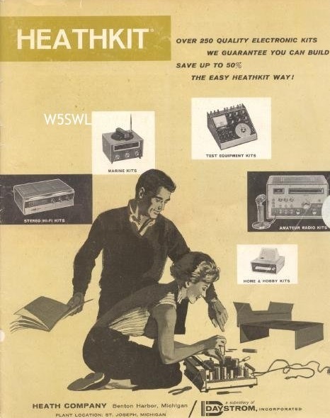
The 60's and 70's were the golden age of electronic kit building. The novice had a great many educational kits to choose from that taught basic skills and electronics theory while assembling a device that could do something useful or entertaining. An advanced builder could use "sweat equity" to inexpensively obtain popular electronic products like HiFi stereo systems, color televisions, CB radios, and automotive test equipment.
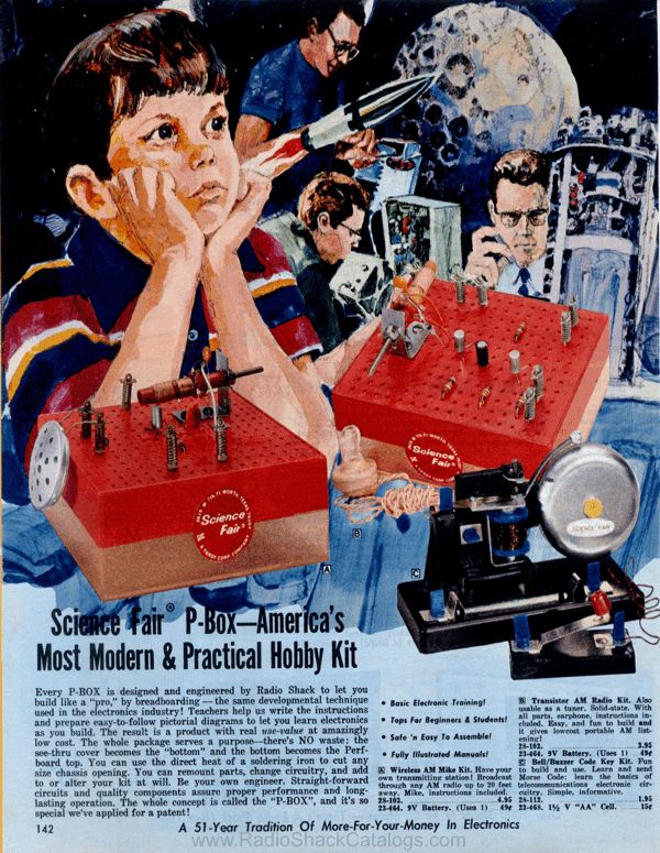
Today there are still quite a few electronics kits available for education purposes, but rapidly evolving features and shrinking components ended the consumer electronics kit business. I would have loved to have assembled some of the products that were popular in the 70's, but unfortunately most of the companies that made all those wonderful kits were gone when I began my career. In honor of a great set of educational Radio Shack electronics project kits available during the 60's and 70's, I've redesigned the original Science Fair brand One Tube AM Radio (Catalog #28-100) using modern components still available from electronics component re-sellers in the US. All of the components in the updated kit can be found on Amazon.
There were many things Radio Shack did extremely well during its prime. It's too bad the company is "history" along with Lafayette Radio, Allied Radio, Heathkit, Popular Electronics, Byte, and many others who were here for a time and are here no more. Their humor, their creativity, hand-drawn artwork... Experimenters young and old, especially in rural areas, are less served by their demise.
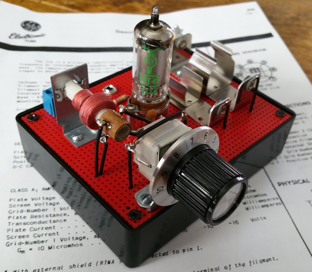
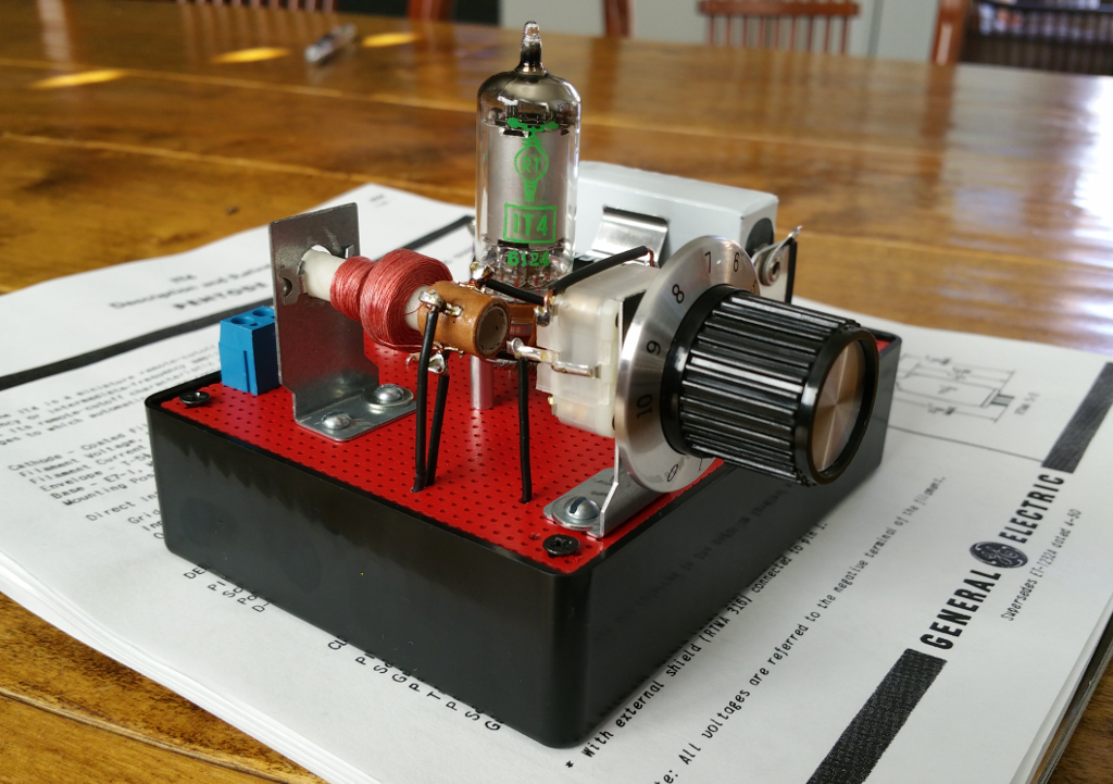
For the nostalgic or the enthusiast who would like to build an updated version of this classic radio, I've included schematics, parts information, assembly documentation, and pictures of a completed and tested One Tube AM Radio based on the original from 1968, which is itself derived from a design attributed to Lee de Forest in 1908. If like me you enjoy walking in the footsteps of the great inventors of the 20th century, you'll love this project.
Just a Song Before I Go...
An original Radio Shack One Tube AM Radio kit was given to me by a mentor of mine when I was still learning how to solder. But I didn't really have the proper tools for electronics assembly work. While putting the kit together, I accidentally broke off one of the tube socket pins. I tried as hard as I could to solder a wire to the little stub of metal sticking out but couldn't. When I went to my local Radio Shack, the One Tube Am Radio kit had been long discontinued. "A 7-pin tube socket? Ha! Good luck kid." So I shelved the kit and moved on. But I never forgot that early failure. So for me this project was a redemption, so to speak.
After redesigning the tuning circuit with available parts and building the radio, I was disappointed in its performance. After checking with a few people online that could remember building the original Radio Shack kit back when it was available, I found the consensus to be that the radio never really worked well. Slightly better than a crystal radio I believe was the usual outcome. I didn't want a nice looking tube radio that didn't work, so I decided to rewire it using some old amateur radio articles published in the 1920's for inspiration. I was very happy to find that the new design presented in this article worked much better than the original. I can easily receive all three local AM stations in my city with a 10ft piece of wire for an antenna and an earth ground connection.
Although I feel my results made the project costs, time, and effort worthwhile I think it wise to present to the reader a few observations and opinions:
1. I recommend this project for the intermediate to expert builder. Moderate soldering skills are required and some metal fabrication must be done for the variable capacitor and tuning coil brackets. Connecting and soldering wires to the mounted tube socket can be a challenge for the inexperienced. Several of the components are fragile and relatively expensive. If you have successfully completed a few projects from scratch using breadboard construction techniques, then you should be good to go for the One Tube AM Radio project.
2. If you decide to build this project, you should have no problem obtaining the parts. I deliberately avoided using rare or hard to find vintage parts in order to save those for the folks that are trying to restore a vintage radio. Instead, I provide component names and part numbers from distributors of new or new-old-stock in volume that are compatible with the original look of the radio as much as possible.
3. The 22.5 V battery I used is the most expensive component of the lot at $25. I chose that battery because I wanted to keep to the original look and feel as much as possible, which required me to spend more money than I would otherwise recommend. By all means feel free to substitute three 9V batteries in series for the 22.5V battery.
Should you decide to use the 22.5V battery I did, you can obtain it from Excell via Amazon (ASIN B009Z1ERAE). This battery works extremely well in the radio, and will run for 4 months of continuous use or more than a year of occasional use. I suspect what Excell has done is connect fifteen 180mAh alkaline button cells in series and secure them to a plastic carrier that is the same size as the old NEDA 215. So perhaps there is some hacking that can be done instead of buying a new one.
4. Current consumption on the 22.5V B Battery is 40uA so it can run quite a long time. However, A Battery consumption on the 1T4 tube is 50mA, in line with the manufacturers specifications. Which means you can expect between one to two days of continuous use and perhaps several weeks of occasional use. Keep a pack of AA's handy.
5. The most significant deviation from the original Radio Shack kit is the use of a tuning capacitor. After many days spent searching through the web for a volume source for the antenna coil, I concluded that it is not possible to obtain one similar to the original without resorting to a rare vintage supplier. So I decided to use an adjustable Miller-style antenna coil from AmplifiedParts.com and tuning capacitor from uxcell.com. The adjustable ferrite slug in the antenna coil I used allows for alignment of the tuning range only. Main tuning is provided by the variable capacitor. But the tuning coil does look enough like the original part to make me happy, and the redesign allows the radio to tune into the Extended AM Broadcast band between 1610 kHz and 1710 kHz, something the original kit wasn't designed to do.
6. This project requires "alignment" in order to set the tuning range between 540 kHz and 1710 kHz. Which means the builder will need a hex alignment tool for the tuning coil. I used a 0.100" hex alignment tool from Aven Tools (Amazon ASIN B001Q4YGQS) which is a nice sturdy kit that has worked well for me. Alignment is best accomplished by setting the coil slug and variable capacitor trimmers as indicated in the "Before You Begin" section. An LCR meter is suggested for the most accurate alignment but is not required.
If you are still with me after all of the above, then let's get started.
Please Note: I have no business relationship with any vendors mentioned in this article. Nothing of financial value was exchanged for any recommendation I make. None of the vendors mentioned in this article provided compensation of any kind during the creation of this project. I will not be compensated in any way if you choose to build this project or purchase components from any vendor I recommend. I simply had a good experience with the vendors I recommend and believe you will too.
Obtain Components Listed in the Assembly Manual Parts List
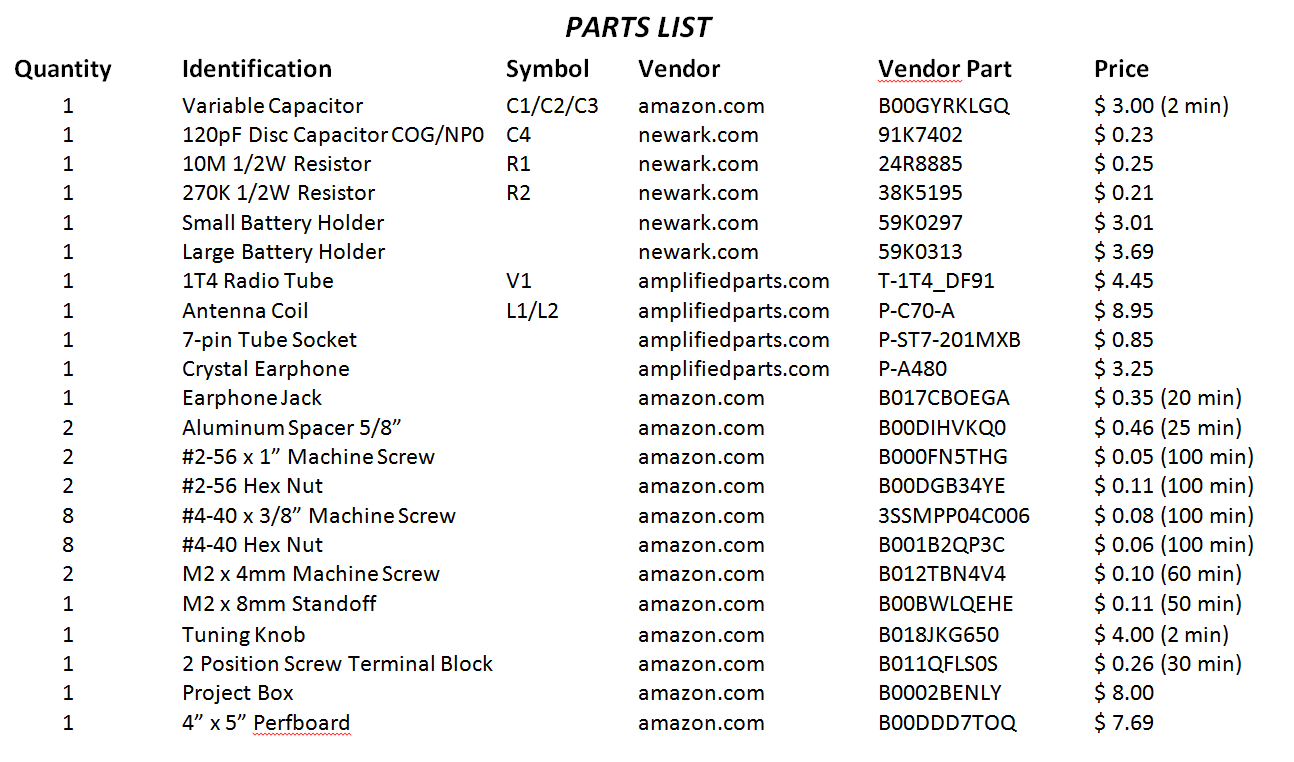
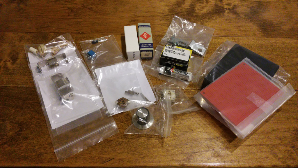
Review the parts list and obtain the components indicated. Everything but a few pieces of hardware are available on Amazon or can be obtained directly from the suppliers indicated at the bottom of the parts list.
Below are a few notes regarding the parts used for the radio:

1. Amplified Parts (www.amplifiedparts.com) is my go-to resource for tons of components used in vacuum tube amplifier and radio circuits. Tubes, knobs, jacks, coils, earphones, resistors, capacitors.. it's all there. They have tons of NOS components in regular inventory, online ordering is easy, and shipping is extremely fast. The critical components of the One Tube AM Radio were all obtained here. I purchased several 1T4 tubes, 7-pin sockets, antenna coils, and crystal earphones from AmplifiedParts and they all work great. The crystal earphone comes with a 1/8" mono phone plug so I added a 1/8" mono phone jack from Amazon. If you like to build, repair, or restore vintage equipment you have to check out Amplified Parts.
2. For bulk resistors used in project building and experimentation, I highly recommend the excellent Joe Knows Electronics (www.joeknowselectronics.com) resistor kit in 1/4W and 1/2W sizes. These kits include the most popular values you will be likely to use with 1% tolerance (which is overkill for basic circuits but nice to have). NOTE: As of 2026, Joe Knows Electronics is no longer in business. I have left the content here for historical purposes. There are many resistor assortments available on Amazon at great prices.
3. I strongly recommend ordering NP0 ceramic disk capacitors from Allied, Mouser or Digikey as they will far outperform most anything you can get on Amazon. The Joe Knows Electronics capacitor kit is an extremely good buy for general purpose capacitors at 645 pieces for $13.00.
4. The variable capacitor (and a lot of other rather old and interesting electronic parts) can be found at Uxcell (www.uxcell.com) which seems an unlikely domain for radio stuff, but they do have a lot of radio stuff that's interesting. I've created a diagram of the variable capacitor below that will help you figure out how to wire it into radios circuits of your own design.
5. The case for the radio I built is a Hammond 1591GSBK ABS Project Box from Amazon.com with a piece of vector breadboard cut to fit on the top and spray painted with high temperature automotive flat red and finished with a semi-gloss clearcoat. I like the look of red on black, and the red color of the breadboard matched the red color of the original pbox kit. It's completely up to you how you want to house and color the kit you build.
6. The knob I used is a Radio Shack product I've had in inventory for decades. Use anything you think is cool that will fit on the varicap shaft. The shaft on the varicap is only about 1/4" long so you will need something to extend it. I used a nylon hex standoff and shaved it down to fit. Use anything you have that gives the knob a confident solid feel.
7. For those curious about the 1T4 vacuum tube, I've included the datasheet I used with the 1T4 from Amplified Parts. The evaluation I did on filament current, plate and grid current/voltage, and Mu parameters for the tube sold to me matches very closely with the parameters in the datasheet. Very useful when doing your own designs.
8. Also below is the datasheet for the antenna coil from Amplified Parts. My measurements show the following:
Primary (Pins 3/4) - 2120uH to 3372uH variable when ferrite is positioned on the primary
Secondary (Pins 1/2) - 163uH to 333uH variable when ferrite is positioned on the primary
Unloaded resonant Q is around 250.
These are the parameters I used to redesign the tuning section of the radio and they were dead on as built.
The datasheet for the 1T4 Tube is >>> HERE <<<.
The datasheet for the Tuning Capacitor is >>> HERE <<<.
The datasheet for the Tuning Coil is >>> HERE <<<.
Before You Begin - Variable Capacitor Alignment
Before you start the build process, the variable capacitor needs to be set to its minimum value by adjusting the position of the trimmer capacitors on the back. If you look closely at the back of the variable capacitor, you will notice 4 small adjustment screws.
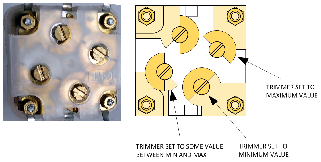
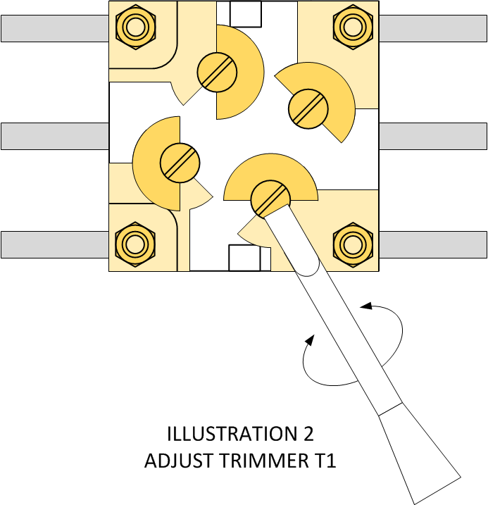
Illustration 1 - Variable Capacitor Trimmer Adjustments
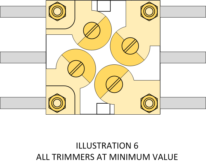
These adjustment screws are provided to fine-tune the range of each section of the variable capacitor. The variable capacitor you will receive may have its trimmers set to minimum, maximum, or some value in between (See Illustration 1). What you need to do is adjust each trimmer to it's minimum value as shown in Illustration 6:
Caution: Avoid applying heavy pressure into the trimmer while turning. If the trimmer is hard to turn in one direction, try to rotate it in the opposite direction. Let the tool do the work.
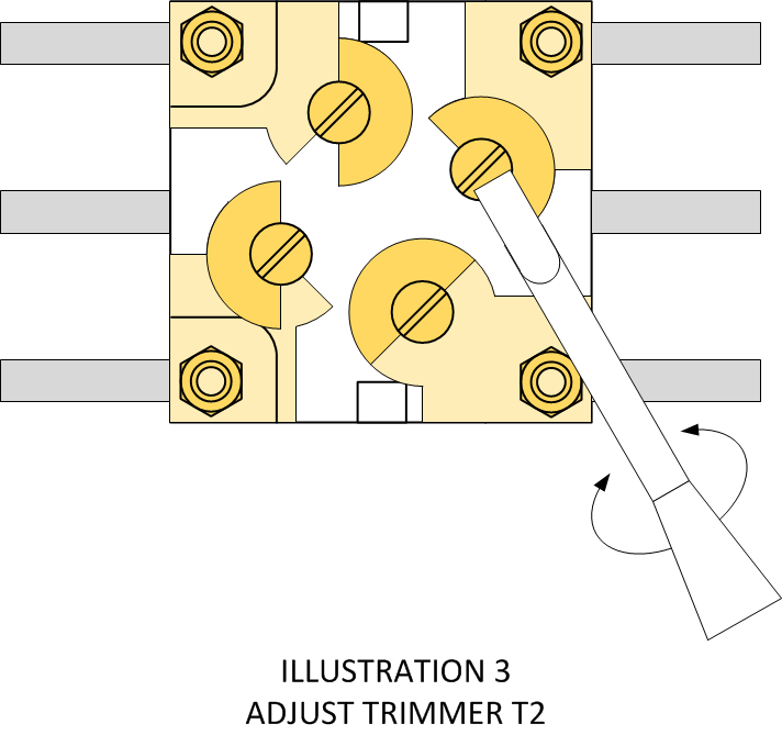
1. Hold the variable capacitor with the trimmer screws facing you. Using a small precision screwdriver or the steel slotted alignment tool from the Aven kit described earlier, turn the T1 trimmer screw clock-wise or counter-clockwise as shown in Illustration 2 until it is in the position indicated in Illustration 3.
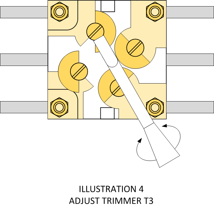
2. Do the same for trimmer T2 (see Illustration 3) until it is in the position indicated in Illustration 4.
3. Do the same for trimmer T3 (see Illustration 4) until it is in the position indicated in Illustration 5.
4. Do the same for trimmer T4 (see Illustration 5) and then verify that all trimmers are in their minimum value position as indicated in Illustration 6.
The variable capacitor is now ready for use.
If you have an LCR meter, the variable capacitor should provide the following range:
Low Value: 18pf to 24pF
High Value: 298pF to 304pF
A document describing the variable capacitor connections is included >>> HERE <<<.
Before You Begin - Antenna Coil Alignment
The P-C70-A antenna coil provides an adjustable ferrite core for fine tuning the inductance of the secondary winding so that the tuning range of the variable capacitor fits comfortably within the AM broadcast band (540 kHz to 1710 kHz). The antenna coil you will receive has not been aligned and requires adjustment before installation. The alignment can be fine tuned after installation. To align the antenna coil, follow the steps below:
Caution: Use only a 0.100" plastic hex alignment tool. A tool of the wrong size will damage the ferrite slug making it impossible to align the antenna coil. Use only the minimum force necessary to rotate the slug. Do not push against the slug while turning. Let the alignment tool do the work. Check the slug position after the first few turns to make sure it is moving in the correct direction (toward the front of the coil). If it isn't, reverse the direction of alignment tool rotation.
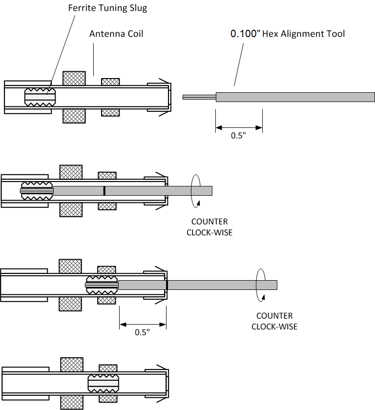
1. Measure 1/2" along the barrel of a 0.100" Hex Alignment Tool starting from the shoulder as shown in the illustration above.
2. Insert the alignment tool into the front of the antenna coil as shown until the alignment tool is fully seated into the ferrite core.
3. Rotate the alignment tool in a counter clockwise direction making sure that the alignment tool is moving out of the front of the coil instead of inward toward the back of the coil.
4. Stop rotation and remove the alignment tool when the top of the ferrite core is 1/2" from the front of the antenna coil.
The antenna coil is ready for use.
If you have an LCR meter, the coil inductance should be between 300uH and 330uH.
A datasheet for the antenna coil is included >>> HERE <<<.
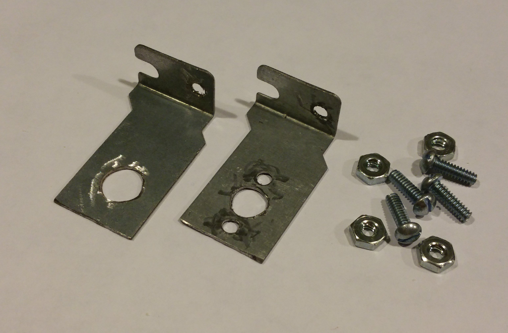
Before You Begin - Fabricate Mounting Brackets
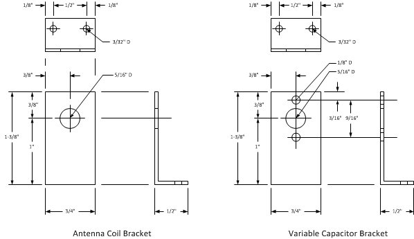
I've included templates for fabricating the mounting brackets used with the variable capacitor and the antenna coil. I used two PC card slot blanks I had laying around and simply cut them to size, drilled holes, and used a Dremel tool to grind off the flash. You can use any soft metal you have in your junk box. Or even a piece of plastic that is shaped like an 'L' bracket will work. Imagination will pay off in this step.
Caution: Always wear eye protection when using power tools. This project is more fun to share with your friends than your eye doctor.
A 1:1 scale printable version of the bracket template is included >>> HERE <<<.
Some Findings on Earphones From Amplified Parts
There is distinct difference between the earphones originally supplied in Radio Shack kits and the ones available today. The original earphones were Rochelle Salt (potassium sodium tartrate tetrahydrate) which had a typical capacitance of around 300pF and an impedance of around 500K Ohms at 1000 Hz. The salt crystals were cut square and bonded to conductive foil on one side, then attached to a conductive conical aluminum diaphragm and center pushrod on the other side. When energized, the salt crystal bends and moves the aluminum diaphragm up and down via the center pushrod.
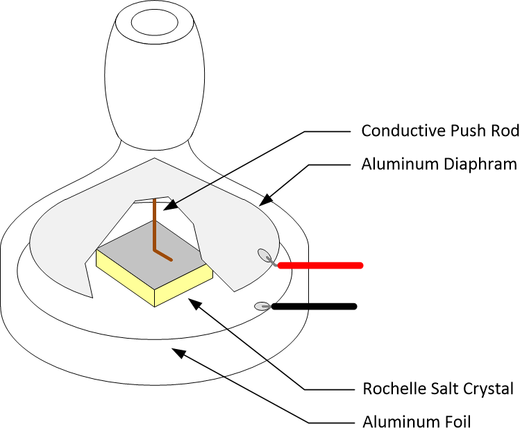
Rochelle Salt Piezoelectric Earphone
The earphones available today are made from a thin ceramic disk composed of barium titanate. A conductive pad is bonded to the back of the disk for the positive lead attachment. A conductive flat aluminum diaphragm is bonded to the front side of the disk and the negative lead glued to the diaphragm. When energized, the ceramic disk expands perpendicular to the diaphragm moving it up and down. These earphones have a typical capacitance of 2500pF and an impedance of around 6K Ohms at 1000 Hz.
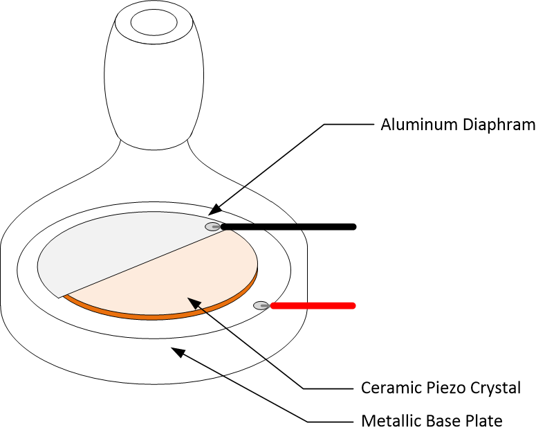
Ceramic Disk Piezoelectric Earphone
There is a huge difference between the impedance of each type of earphone so I thought I'd compare the performance of each to determine what the differences would be. I found and purchased one of the original Radio Shack earphones in good condition, and purchased several new earphones from Amplified Parts. My first test was an impedance check with various source impedances to determine the roll-off for old and new earphone.
As expected, the original Radio Shack earphone capacitance is around 300pF. Impedance falls where expected; around 500K Ohms at 1000 Hz, around 100K Ohms at 5000 Hz, 10K Ohms at 50 kHz, and 1K Ohms at 500 kHz. Impedance at 1MHz was approximately 1K Ohms.
The new ceramic earphone from Amplified Parts came in at 24nF with impedance of 500K Ohms at 10 Hz, 100K Ohms at 60 Hz, 10K Ohms at 600 Hz, and 1K Ohms at 6000 Hz. Impedance at 1MHz was approximately 7 Ohms. The new earphone has an odd resonance (see photo below) between 3000 and 4000 Hz but rolls off relatively smoothly.
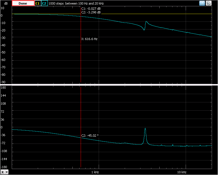
Ceramic Earphone Frequency Response
At first I thought the new earphone might not work well with a 1N34 crystal radio or the One Tube radio described in this article. However after constructing both and trying each headset in a blind test, I couldn't tell that there was a difference in sound volume.
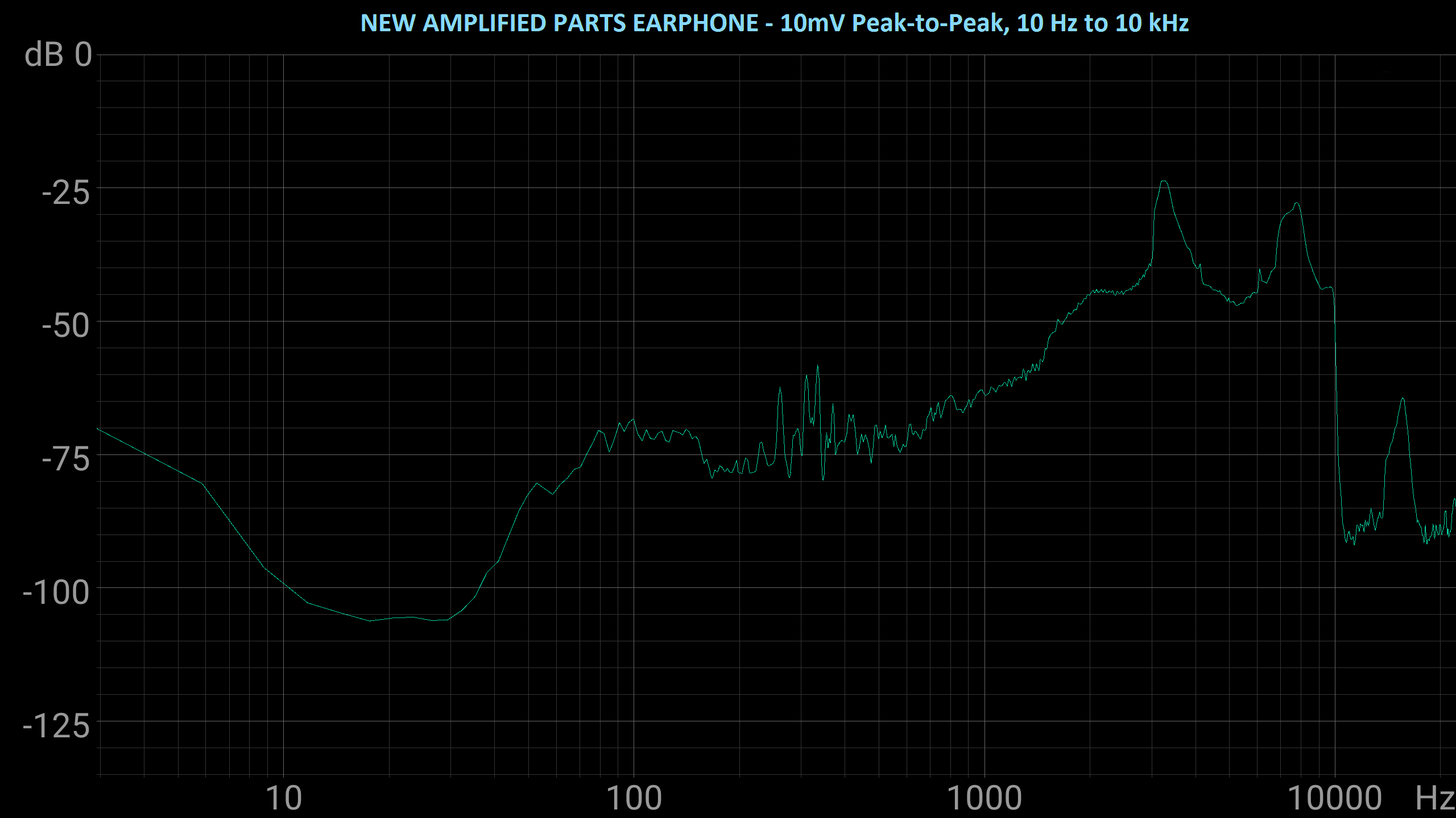
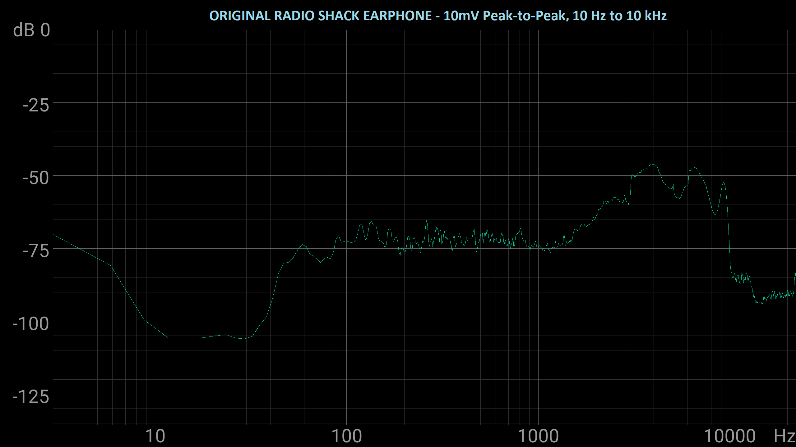
So I decided to compare the sound pressure level from each earphone with a microphone, sweep generator, and spectrum analyzer set as flat as possible between 10 Hz and 10 kHz. As seen in the two images below, the new Amplified Parts earphone is more efficient at converting the sweep generator signal into sound. So I figured I was onto something.
In the next test, I compared sound levels in a radio test circuit with 100K Ohms output impedance to see if there was a significant difference between the original Radio Shack earphone and the new Amplified Parts earphone.
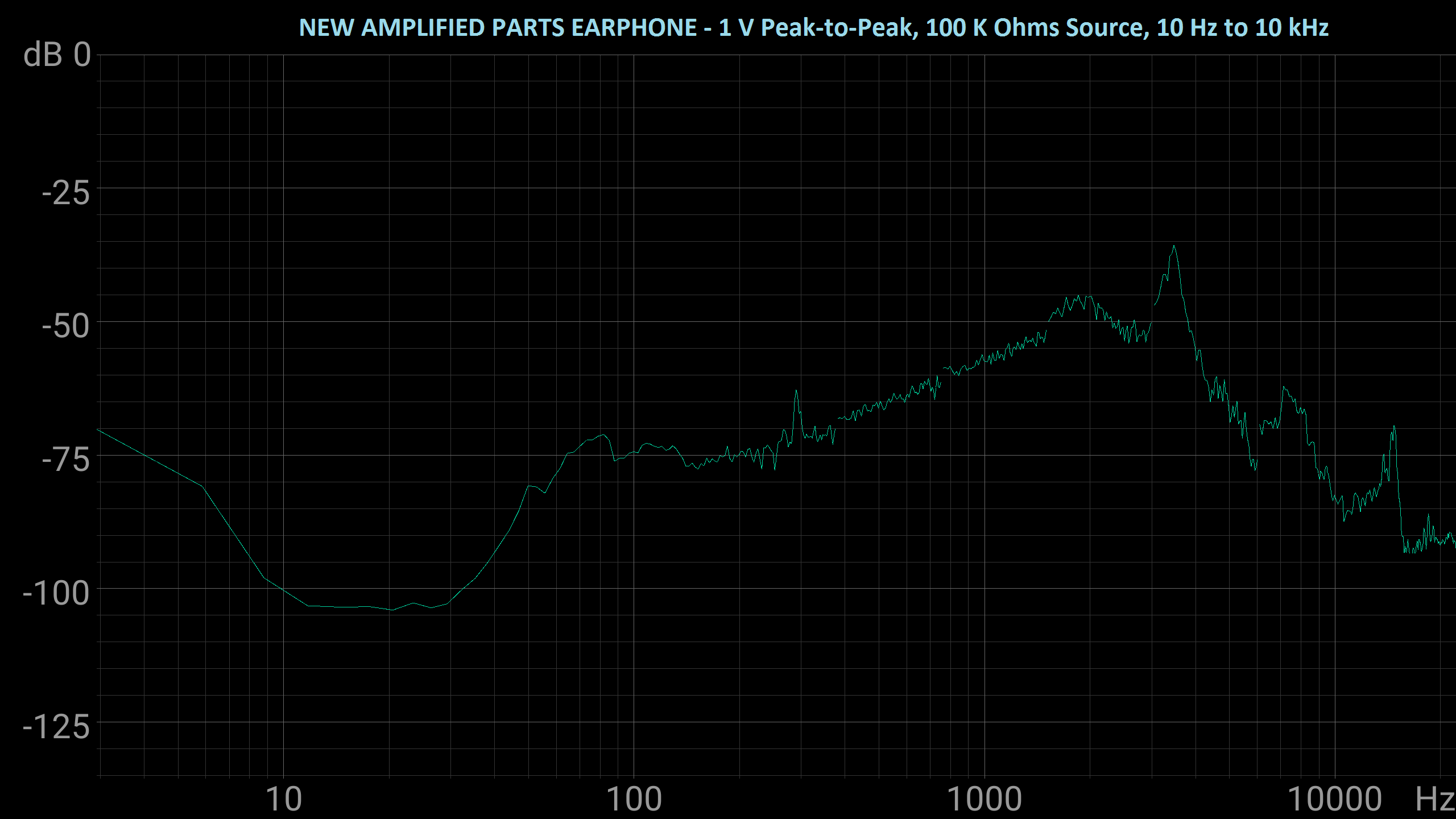
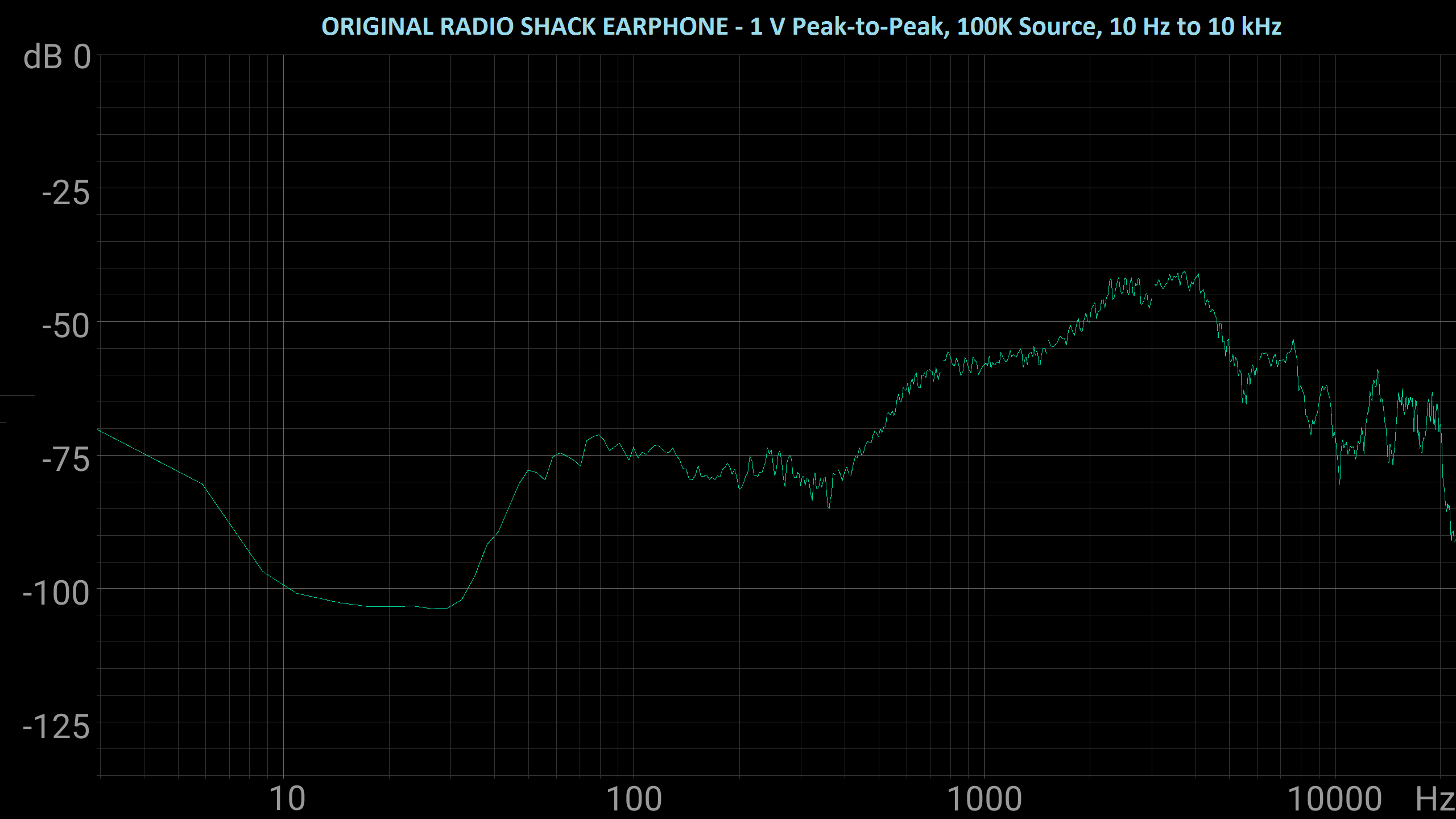
The Amplified Parts earphone loaded down my radio test circuit far more than the original Radio Shack earphone did, but appears to have almost made up for the impedance losses with conversion efficiency, which I think is why I'm not able to subjectively tell the difference between the two when doing a blind listening test.
ONE THING TO KEEP IN MIND, THOUGH:
I've bought several of these and had no issues up until just recently when one failed on me after a few days of radio listening. The two that are still working I've been using for over a year now. So I think there are some occasional quality issues with these that warrant getting more than one when building a project that uses them. I recently placed an order for three just to have extras on hand. You might want to do the same.
Review the Schematic to Become Familiar With the Radio Design
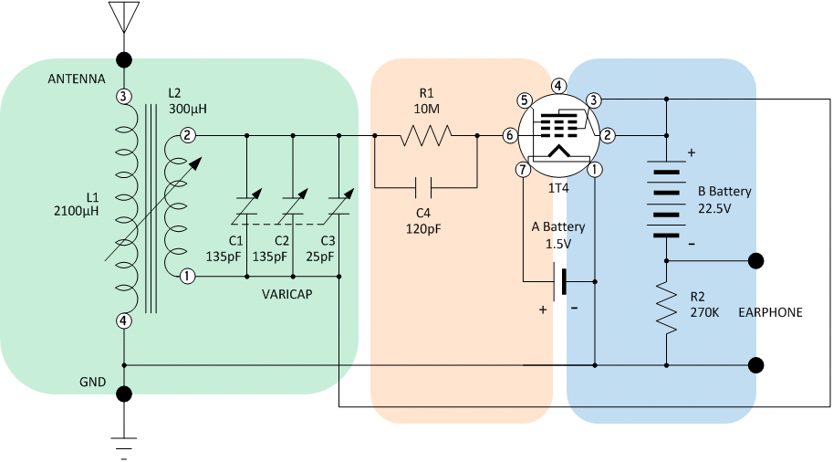
The original Radio Shack design used a variable inductance tuning coil and a fixed capacitor to form the LC parallel resonant tuning circuit. However that variable tuning coil is no longer available from a specialty electronic component retailer. However I was able to find a Miller-style P-C70-A antenna coil (sold by Amplified Parts) with sufficient inductance to permit a variable capacitor to set the LC resonant frequency in the AM broadcast band. The P-C70-A antenna coil has a similar appearance to the original Radio Shack part so I thought it would be fun to redesign the radio using available parts.
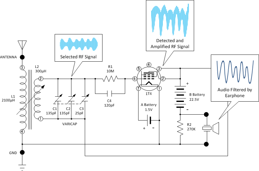
Tuning Section
L1 (primary) of the antenna coil is used to lightly couple the long wire antenna to the LC tuning circuit composed of L2 (secondary) and the parallel combination of variable capacitor sections C1, C2, and C3 (see the Varicap datasheet for more information). The ferrite alignment slug is adjusted so that the inductance of L2 is approximately 300uH. The trimmer capacitors of C1-C3 are adjusted to their minimum value so that the combination of C1-C3 provides a variable capacitance between 25pf and 300pF. Using the standard formula for parallel LC resonant frequency and plugging in the values for L and C results in the following tuning range:
Fc = 1 / [ 2 * pi * sqrt ( L * C ) ]
where L = .0003 Henrys and C varies between .000000000025 Farads and .0000000003 Farads.
Fc1 = 1 / [ 2 * pi * sqrt ( .0003 * .0000000003 ) ] = 530 kHz
Fc2 = 1 / [ 2 * pi * sqrt ( .0003 * .000000000025 ) ] = 1837 kHz
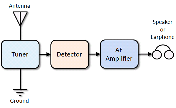
Since the medium wave broadcast band in ITU Region 2 (Americas) is 540 kHz and 1710 kHz with 10Khz spacing, my choice of inductor and capacitor worked out well for the tuner section (see block diagram above).
Detector Section
A popular AF detector in the 1920's was the grid leak detector composed of the 1T4 vacuum tube and the parallel combination of R1/C4. The Grid (Pin 6) and Cathode (Pin 1) of 1T4 form a diode that is forward biased by the B battery connected to L2. The large size of R1 (10 Meg Ohm) ensures that the Grid voltage with respect to the Cathode is held at approximately 0V with no signal. This causes the tube Cathode and Plate (Pin 2) to act almost like a closed switch resulting in a fixed voltage across resistor R1 of around 10V. When a station is tuned in, the alternating carrier wave received is directly coupled to the tube Grid (Pin 6) through capacitor C1. On the positive half cycles of the carrier wave the tube Grid is forced positive, but since the tube is already saturated almost no change in current occurs at the Plate output resulting in almost no voltage change across resistor R2. However, on the negative half cycles of the carrier wave, the tube Grid is forced negative which reduces the current across the Cathode/Plate resulting in a voltage change across resistor R2. The top half of the carrier is removed leaving the bottom half of the carrier intact with a copy of the audio signal modulated on it. The internal capacitance of the earphone (2500 pF) filters out the RF carrier wave leaving only the original audio signal. With the earphone connected, the audio signal voltage is converted into sound waves in the earphone that can be heard by the radio listener.
AF Amplifier Section
A basic operating characteristic of a vacuum tube is that small changes in Grid voltage result in large changes in Cathode/Plate current. When the Plate is connected to a load resistor like R2, large changes in Plate current cause large changes in load resistor voltage. Thus a small change in input voltage on the Grid results in a large change in output voltage on the Plate, which in electronics is called Amplification. The 1T4 vacuum tube works as an amplifying diode detector with a gain of around 100. This helps the radio perform better than a simple crystal radio.
Advantages of this radio design:
1. Relatively simple with few parts but better performance than the even simpler crystal radio.
2. Receives all local stations with a short 10' antenna and a ground connection.
Disadvantages of this radio design:
1. AC impedance of the grid leak detector loads the LC tuner which reduces selectivity of the radio.
2. Gain is insufficient for non-local stations. Regenerative radios achieve gains greater than 10,000 but add complexity to the circuit and station tuning process.
3. A grid-leak detector is easily overloaded by strong local stations resulting in noticeable distortion in the output. Making the antenna only as long as needed is important.
Review the Circuit Board Layout
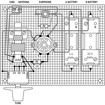
The Assembly Manual provides a step-by-step checklist for installing and soldering each component to the perfboard. I've used point-to-point wiring with 20 AWG solid hookup wire. Some of the connections can be made with just the component leads. Power, ground, and signal bus leads are best done with lengths of hookup wire. Parasitic capacitance isn't much of an issue for the frequencies this radio will operate at and I've already compensated for most of these in the design. When built, the radio is free of unwanted oscillation or noise.
When it comes to wiring, try to be as neat as I've indicated in the assembly manual. You don't have to be the world's best soldering artist but there's no good reason to do the work half-way. Go all out and make your radio look as good as you can.
Follow the Steps in the Assembly Manual to Complete the Radio
To make the assembled radio look more like the original Radio Shack PBOX kit, I purchased some flat red and satin clear spray paint. I've applied two coats of red and two light coats of clear which I think gives the perfboard a natural texture. Almost like it was made that way.
Use any color you wish but I recommend not skipping the clear coat if you paint the perfboard with flat colors. Flat paint tends to show marks and texture changes at the slightest touch. The natural vector board finish also looks nice so you don't have to use paint of you don't want to.
The perfboard specified in the parts list is too large to fit onto the Hammond case so some trimming is required as indicated in the images below. Follow the steps below to prepare the perfboard before installing components:
1. Using a sharp edge, carefully score the perfboard along the TOP ROW and BOTTOM ROW row of holes all the way to the end of the board. Run the sharp edge over the score line several times until it penetrates 1/4 to 1/2 way through the perfboard.
2. Using a sharp edge, carefully score the perfboard along the RIGHT COLUMN and LEFT COLUMN of holes all the way to the end of the board. Run the sharp edge over the score line several times until it penetrates 1/4 to 1/2 way through the perfboard.
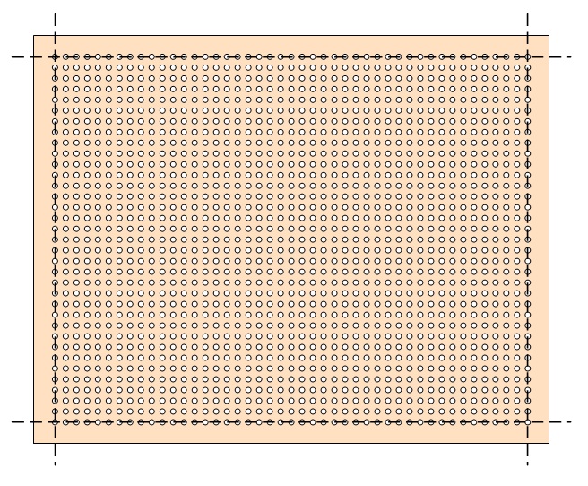
Score edges of perfboard along dashed lines
3. Using a small pair of pliers, carefully bend the TOP ROW section back away from the score line. Work with one end of the TOP ROW, moving to the center, and then the other end. The TOP ROW section will eventually break away from the perfboard.
4. Using a small pair of pliers, carefully bend the BOTTOM ROW section back away from the score line. Work with one end of the BOTTOM ROW, moving to the center, and then the other end. The BOTTOM ROW section will eventually break away from the perfboard.
5. Using a small pair of pliers, carefully bend the RIGHT COLUMN section back away from the score line. Work with one end of the RIGHT COLUMN, moving to the center, and then the other end. The RIGHT COLUMN section will eventually break away from the perfboard.
6. Using a small pair of pliers, carefully bend the LEFT COLUMN section back away from the score line. Work with one end of the LEFT COLUMN, moving to the center, and then the other end. The COLUMN section will eventually break away from the perfboard.
Carefully break apart perfboard edges along score lines
7. Using an Exacto knife, match the trimmed perfboard with the Hammond case and enlarge holes at the corner to match with the corner mounting holes in the case. Work slowly and carefully with minimal pressure to avoid breaking the corner piece.
8. Place the potentiometer mounting brackets onto the perfboard and enlarge holes in the perfboard to match the holes in the brackets. Work slowly and carefully with minimal pressure to avoid cracking the perfboard.
Cut holes for case and bracket screws
9. Spray paint the perfboard with the color of your choice or leave it natural. It's your choice.
Paint with desired color
I typically use flat red followed up with 2 to 3 coats of gloss clear, but feel free to use any color that you like best.
When the perfboard is finished, follow the step-by-step instructions in the assembly manual <<< HERE >>>.
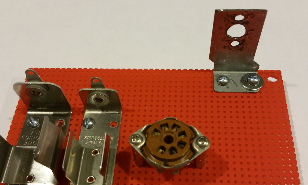
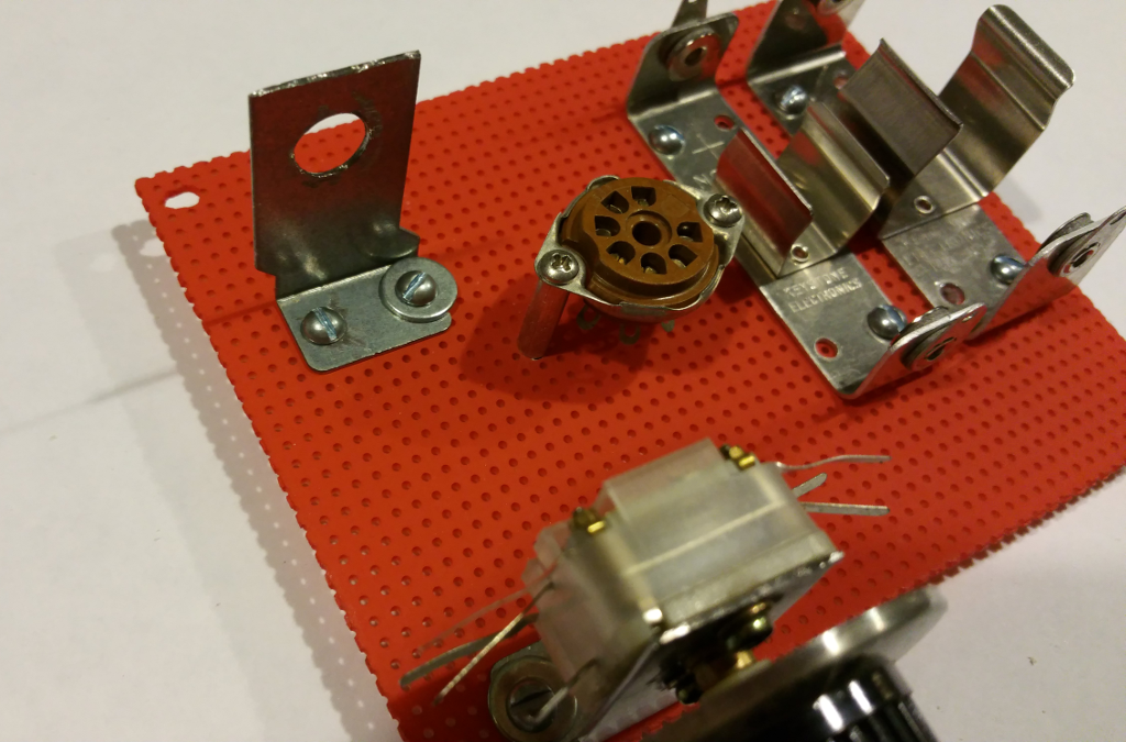
Installation of the Battery Holders
The above is what your radio should look like after the battery holders have been mounted. The battery holders have four screw holes in them, but you only need to use two screws to mount the holders to the perfboard: One in the upper left and the other in the lower right. I just placed the holders in position and marked the perfboard holes with a Sharpie pen. Next I used an Exacto knife to enlarge the holes. Use caution, work slowly, and watch the sharps!
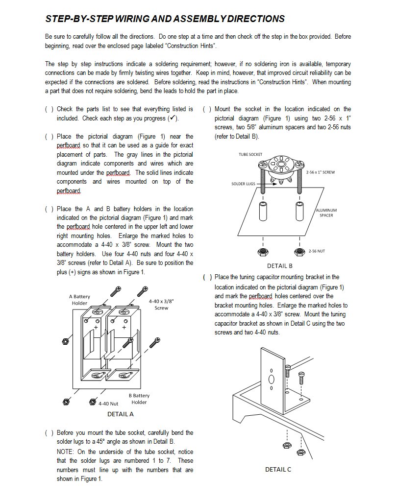
Tube Socket Prepared and Mounted
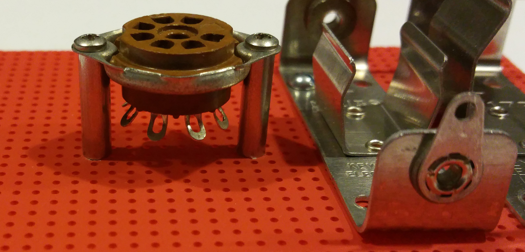
Before you mount the tube socket, very carefully bend the lugs out a little so that it is easier to attach wires to them and solder the connections. Don't do like I did my first time and break one off (man that was soul crushing). Just a little bend about 45 degrees is all that's needed.
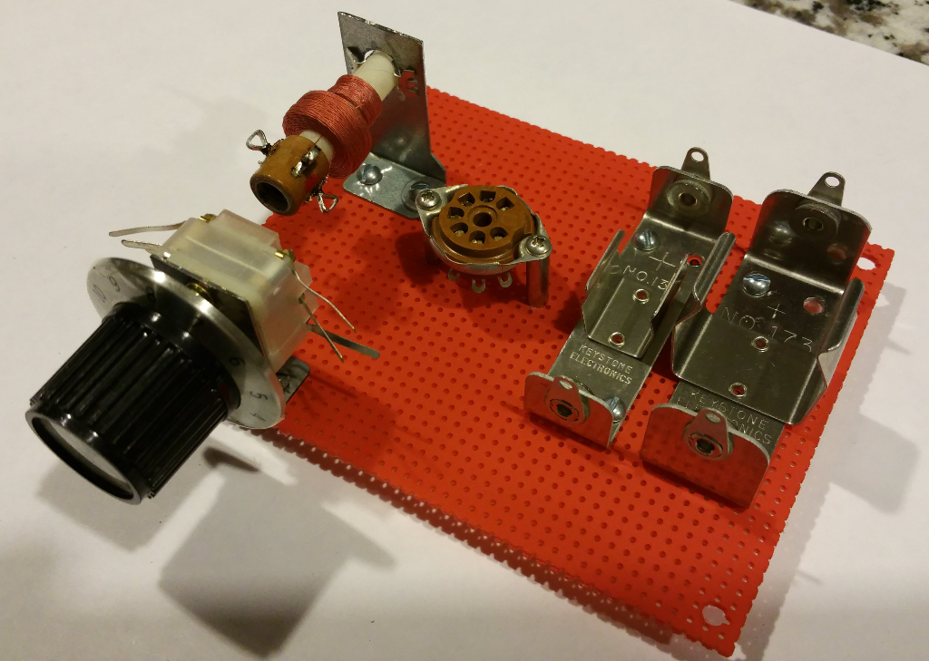
Variable Capacitor Bracket Installed
The above photo shows the variable capacitor bracket installed. Mine has the funny offset shape at the bottom because it's an old PC card slot blank. Yours will likely be different from mine depending on the materials you use. Just make sure it's tall enough so that the variable capacitor body will miss the perfboard mounting screws. And that the bracket is mounted close enough to the edge that the tuning knob can be tightened on the variable capacitor shaft without binding against the case. I've included a 1:1 scale drawing below to help you make brackets similar to mine.
Variable Capacitor Mounted on the Bracket
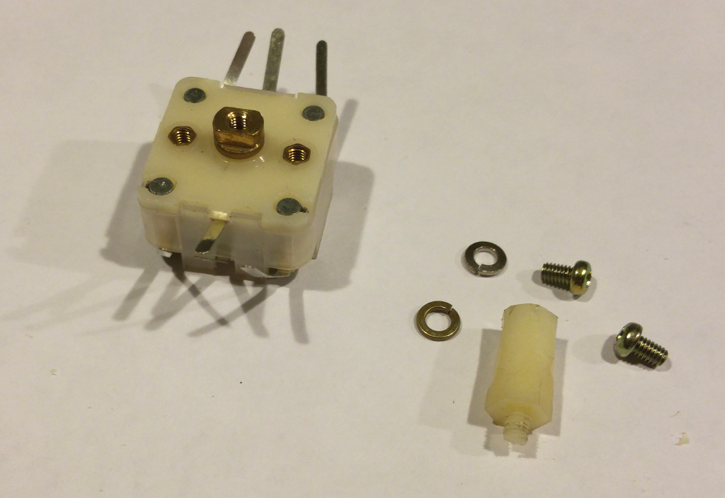
It's very important to use the proper screw length for the variable capacitor mounting holes. Screws that are too long will damage the variable capacitor. Always carefully test fit the screws to make sure they do not intrude into the case. Add some washers if you feel the screws may be too long based on the thickness of the material you use for the bracket.
I used an old nylon hex standoff from my junkbox for the variable capacitor shaft extension. The standoff was too thick to fit into the knob shaft so I whittled it down to size with an X-Acto knife, using extreme caution not to whittle down my thumb in the process.
Antenna Coil Bracket Mounted
I test-fit the antenna coil in the bracket mounting hole before attaching the bracket to the perfboard. On mine I needed to expand the hole just a tiny bit and clean up the flash with my Dremel tool to get a nice tight fit. Don't push the antenna coil all the way in until the bracket is mounted or you might have trouble reaching the mounting screws. It's not easy getting the coil off the bracket once it's on.
Antenna Coil Mounted on the Bracket
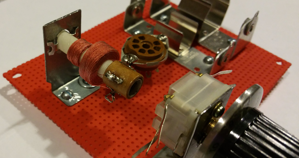
Now it's starting to look like the radio I remember. Be sure that the red dot on the antenna coil is facing directly toward the tube socket.
Soldering in the Grid Leak Detector Components
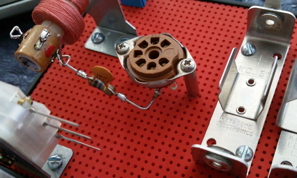
Just twist the capacitor leads around the resistor and solder. Then solder one end to tube socket pin 6. This is one of the hardest soldering tasks in this project. Once you have this and the rest of the tube socket pins soldered it's pretty easy to do the rest of the project.
A word from the soldering iron police: When you've finished using the soldering iron after turning it on, always remember to turn it back off again. If it's already off... then just walk away!
Solder Variable Capacitor Sections C1 Through C3 Together
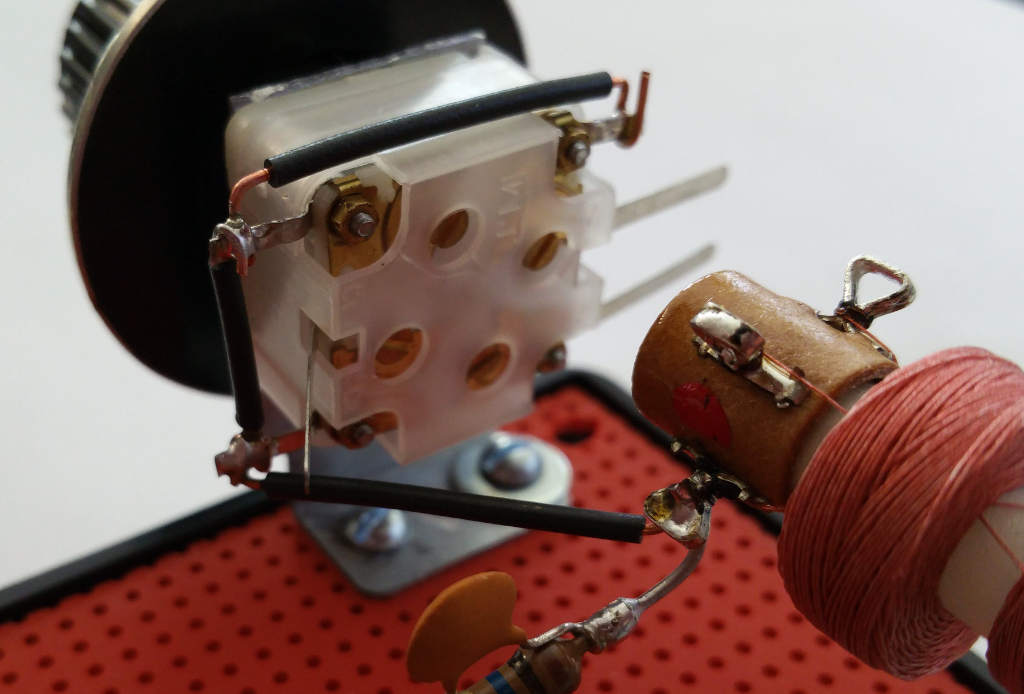
I've included a detail photo of this step as it might be a little more clear what's required and why. The variable capacitor for this project is actually 4 variable capacitor sections in one package. Two of the sections (C1 and C2) vary between 5pF and 135pF each. The remaining two sections (C3 and C4) vary between 5pF and 25pF. By combining these sections individually, in series, or in parallel you can make a variable capacitor with 10 different ranges (several of which are illustrated in the variable capacitor document included in an earlier step). These ranges can be fine tuned with 4 trimmer capacitors included on the back. This is a very versatile component, but it requires a little bit of wiring to get all the sections connected together the right way.
In this radio design we need to connect sections C1, C2, and C3 in parallel. If you observe the photo above, you can see that I have soldered a wire from the pin at the bottom left (C1) to the pin at the top left (C2). And I've soldered another wire from the pin at the top left (C2) to the pin at the top right (C3). The capacitor sections are all tied together internally at the three COM pins in the middle of the variable capacitor body. So by soldering these pins together, I have effectively placed capacitor sections C1, C2, and C3 in parallel. Since the values of capacitors in parallel add together, I've built a single variable capacitor with a range of 15pF to 295pF plus the value of the trimmer capacitors on the back which vary between 1pF and 10pF. In a previous step, I indicate how to set the trimmer capacitors to their minimum value, which makes the final capacitance range between 18pF and 298pF. The actual range will vary slightly due to manufacturing tolerances, but so will stray capacitance in the circuit you build. When doing the design calculations for tuning range, always allow for some room to adjust one way or the other.
The Finished Radio
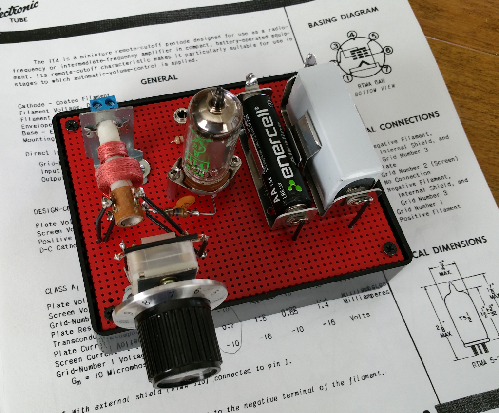
The assembly instruction document will walk you through each wiring step until your radio is completed and ready to power up. All you need to do when finished is double check your work to be certain everything is connected in the right place and well soldered.
After that, connect the antenna and ground connection, plug in the earphone, install the batteries, and tune in the stations.
I really like the look of the finished radio and am happy with it's performance. It's nowhere near as good as a modern superheterodyne, and not quite as good as a regenerative radio, but that's not the point. The point was to build a working radio of the type common in the early 1920's and get a sense for what it was like to use and listen to one; to walk in the footsteps of the people that invented radio. And, enjoy a useful device that looks vintage but is made by hand with off-the-shelf parts. The same way many radio amateurs did 100 years ago.
I hope you will enjoy this project as much as I have.
Some Comments About the AM Broadcast Band
Finding stations nearest you
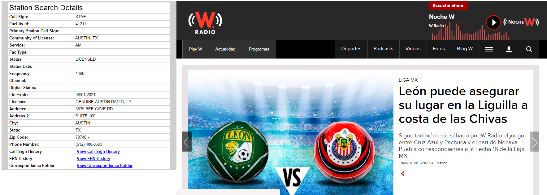
If you are wondering what AM radio stations are nearest you, what frequencies they are broadcasting on, what content is broadcast, and what the operating daytime and nighttime power levels are then you might find the following FCC resource of interest:
https://www.fcc.gov/media/radio/am-query
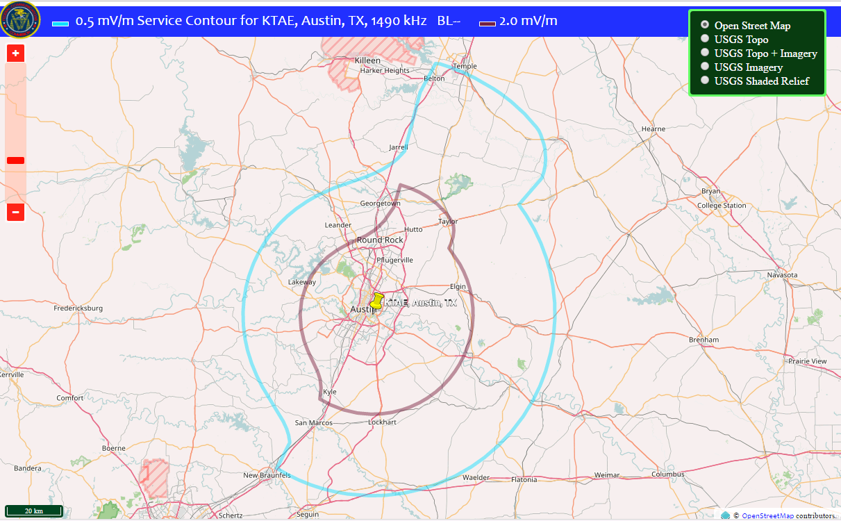
By entering your city and state in the form, you can select a simple or detailed listing of the stations in your area. For example, in my city of Austin, TX there are three stations nearby that broadcast 24 hours a day on 590 kHz, 1300 kHz, and 1490 kHz. I was able to receive these three stations during the day, but two of them were stronger. After reviewing the list the reason was obvious: Two stations (KJBJ and KVET) are licensed for 5KW. The third station (KTAE) is licensed for only 1KW.
You can look up the station service area map to see how strong the radio signal is in your area (see image above). And you can find out more information about the station such as the current owner, number and location of antennas, how long the station has been licensed, how station ownership has changed over time, and probably a lot more than you want to know about a radio station.
I use the FCC data to determine what to expect from the radio's I build and whether or not my tuning is on target.
AM Broadcasts during the Day
During the day, ultraviolet radiation from the sun causes heavy ionization of three layers within the upper atmosphere (the ionosphere). The lowest layer, called the D layer, easily absorbs the energy of AM radio waves and confines AM broadcasts closely to the surface of the earth. These AM "ground waves" are attenuated as they pass over the surface of the earth depending on soil conductivity (sea is best, cornfield is good, city is worst), and are gradually refracted into the earth where they are eventually absorbed. The result is that useful daytime AM radio service is limited to a radius of no more than about 100 miles. If you were wondering why your homemade AM radio can't pick up anything but nearby stations, it's not your radio. It's the way AM works. During the day.
AM Broadcasts at Night
At night when ultraviolet radiation from the sun is no longer present, the D and E layers of the ionosphere almost disappear leaving only the F layer, which due to height and composition make it an excellent reflector of radio waves below 10 MHz. At night, AM radio waves can travel high into the atmosphere and be reflected back to earth hundreds of miles away. These AM "sky waves" could cause massive interference if every station were to transmit at full daytime power. To prevent this, the FCC requires most stations to reduce transmit power at night. For example, in my area there are two stations licensed for 5KW during the day, but only 1KW at night. The exception to this rule are Clear Channel stations (not to be confused with the former Clear Channel Communications company now known as iHeartMedia Inc). Clear Channel stations were licensed under FCC intent to provide radio service to rural areas and create a cross-country communications system for use in the event of a national emergency. In the US, all Clear Channel stations are limited to a maximum power of 50KW. However, in Mexico many Clear Channel stations operate at 100KW and higher, which is why you have a good chance of receiving music and news from Mexico City at night.
Troubleshooting Your Radio
If you build the radio and don't hear anything, immediately remove the batteries and try the following checklist to find the problem:
1. Test the earphone. With a multimeter set to Ohms and the earphone loosely in your ear, measure the resistance across the earphone jack conductors. If you hear a slight clicking sound touching the multimeter leads to the earphone jack conductors, the headphone is most likely working.
2. Verify that the batteries were inserted correctly. The (+) end of each battery points at the top of the radio when the tuning knob is facing you. Insert the batteries in the direction indicated and test station reception again. If you don't hear a station, immediately remove the batteries.
3. Insert the batteries in the battery holder and use a multimeter set to DC Volts to check the voltage on each battery by measuring from the battery holder lugs. If you do not observe approximately 1.5V across the A Battery and approximately 22.5V across the B Battery, immediately remove the batteries and check for loose connections or solder at the battery holders. If there are no wiring errors, one or both batteries may be dead or damaged. Insert fresh replacement batteries and repeat Step 3.
4. With a multimeter set to Ohms and the A and B batteries removed, check the resistance across the A Battery holder terminals. If you observe a high resistance greater than 40 Ohms, double check the A Battery wiring with the assembly manual. Look for miswiring, cold solder joints, missing solder, broken wire, or other wiring related problem. If you observe 0 Ohms on the multimeter, remove the 1T4 tube from its socket and take the measurement again. If you still observe 0 Ohms on the multimeter, double-check all wiring for errors and look for any solder bridges, wire clippings, or unclipped wires under the tube socket. If the multimeter only measures 0 Ohms with the 1T4 tube inserted, the 1T4 tube may be bad. Insert a replacement 1T4 tube and repeat Step 4.
5. With a multimeter set to Ohms and the A and B batteries removed, check the resistance across the B Battery holder terminals. If you observe anything other than a very high reading (1 Meg Ohm or higher), double-check all wiring for errors and look for any solder bridges, wire clippings, or unclipped wires under the tube socket.
6. Verify the 1T4 tube is inserted fully in it's socket and then Insert the A and B Batteries into the battery holder. Wait 5 seconds and then with a multimeter set to DC Volts, measure the voltage across 270K resistor R2. Remove the A and B Batteries. The measured voltage should have been between 9V and 12V. If the measured voltage was not within this range, check the color codes on R1 and R2 to verify they are the correct value. Double-check all wiring and verify no bad solder joints, missing solder, loose connections, or broken wires are found.
7. Using a multimeter set to Ohms, check the resistance across tuning coil L1. The resistance of L1 should be approximately 42 Ohms. If the multimeter measures much less than 42 Ohms or 0 ohms, double-check all wiring at the antenna coil. Look for hard to see solder bridges, wiring errors, wire clipping, or unclipped wires touching. If all wiring is correct, unsolder one of the wires to L1 and measure the resistance of L1 again. If the measured resistance is still much less than 42 Ohms then the tuning coil is likely bad. Replace the tuning coil, insert batteries and the earphone, and try to receive a station. If the measured resistance of L1 is very high (> 100 Ohms), then the antenna coil is likely bad. Replace the tuning coil, insert batteries and the earphone, and try to receive a station.
8. Using a multimeter set to Ohms, check the resistance across tuning coil L2. The resistance of L2 should be approximately 10 Ohms. If the multimeter measures much less than 10 Ohms or 0 ohms, double-check all wiring at the antenna coil. Look for hard to see solder bridges, wiring errors, wire clipping, or unclipped wires touching. If all wiring is correct, unsolder the wire from the Variable Capacitor COM pin to Pin 1 of L2 and measure the resistance of L2 again. If the measured resistance is still much less than 10 Ohms then the tuning coil is likely bad. Replace the tuning coil, insert batteries and the earphone, and try to receive a station. If the measured resistance of L2 is very high (> 100 Ohms), then the antenna coil is likely bad. Replace the tuning coil, insert batteries and the earphone, and try to receive a station. If the measured resistance of L2 with Pin 1 unsoldered from the variable capacitor is approximately 10 Ohms, verify all wiring at the variable capacitor. If all wiring is normal, the variable capacitor may be shorted. Remove the variable capacitor and verify that the mounting screws are not too long. Check the resistance of each capacitor section between C1, C2, C3, C4, and COM. If any capacitor section measures 0 Ohms, replace the variable capacitor.