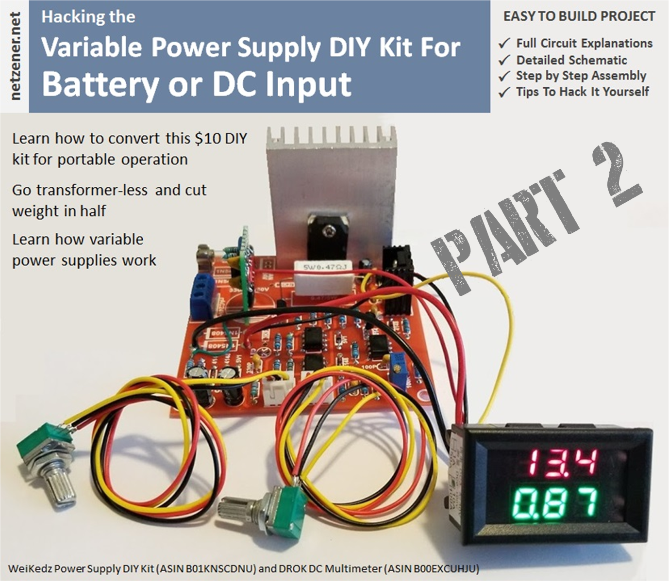
This is the second installment of the Portable Variable Power Supply article. In Part 1, I described in detail each building block of the Weikedz power supply kit and highlighted the strengths and weaknesses of the design. Now in Part 2, I'll show you how to use all of the information gained to adapt the Weikedz power supply for portable applications.
Batteries for portable devices

My initial concern with this project was finding a reliable supplier of rechargeable cells that were small, light, easy to use, and cost effective. Turns out a totally different problem would lead me to the exact product and company I needed:
While I was working on this project, one of the battery packs failed on my DeWalt 12V drill/screwdriver. The thing cost me $90 bucks at Home Depot about 18 months ago so I was hoping to find a replacement pack for maybe $20 to $30. Ha. No such luck. The best I could do was $60 for a single pack from DeWalt.
For that price I might as well buy another screw driver. But then I thought, "There has to be a way I can avoid playing the manufacturers planned obsolescence game." So I ignored the dire warnings in bold large print on the manual and disassembled the failed battery pack. Wouldn't you know it was stuffed with three 18650 cells in series and a little charge control circuit board. Checking voltages on each revealed one cell with zero volts; open circuit.
A quick google search and I had thousands of hits. But one vendor popped to the top with exactly the cell I needed: liionwholesale.com
They had the exact part number I needed for just a few bucks. They processed my order on a Sunday (no kidding... Sunday), and shipped first thing Monday morning. The cell was a perfect fit and immediately restored my battery pack to operation. Now I don't have to avoid rechargeable tools because the manufacturers want exorbitant prices for a battery pack. The batteries used for the Portable Variable Power Supply project were ordered from liionwholesale.com. Give them a try because they have a huge selection of protected, unprotected, low ESR, and high capacity cells. And some really good prices as well.
A quick re-summary
The point of the previous article was to deconstruct the WeiKedz Variable Power supply and examine each function block and component to describe what they do. There is very little informational in detail available on the WeiKedz product and I was hoping to cast more light on it, because I think it is a good product. It only suffers from some optimistic specifications. If you are unfamiliar with power supply design, or you needed a lot more information before giving the power supply a try, I hope the previous sections have helped.
I purchased the WeiKedz kit because I needed an analog variable power supply that could run on LG M26 2600mAH 18650 protected button top batteries. Four of these in series would provide a battery voltage between 12.8V and 16V with a nominal voltage around 14.8V. Protected cells make charging and discharging the cells easier than providing a balance charger. I only need the power supply to provide a variable 0 to 10V at 0 to 1A output current, so the lower ESR of unprotected cells wasn't an advantage in my application.
The specifications I was hoping to achieve were:
Input voltage: 14.8VDC nominal (12.8Vmin to 16.8Vmax)
Input current: 1A (max)
Output voltage: 0-10VDC nominal (0 to 12V max)
Output current: 4mA to 1A (adjustable)
Output regulation: 0.01%
However if you remember from the introduction of Part 1, the WeiKedz power supply was designed to be powered from a transformer only. A negative 5V power supply generated from the transformer is used by the Error Amplifier, Current Limiter, and Current Pass functions. Running the WeiKedz supply on batteries without modification is not possible.
But as you'll see in the next sections, the solution to this problem was actually an easy one. So let's get started.
1. Battery Mod - Rectifier Circuit
To convert the Rectifier Circuit to battery operation, we first eliminate all of the components that aren't needed. This saves weight, reduces cost (i.e. unused parts can be used for another project), and makes space available for some new components.
The components that are not needed are:
- Rectifiers D1 through D4 (1N5408)
- Resistor R1 (2.2K 1W)
- Capacitor C1 (3300uF 50V)
Do not install the components listed above.
Optional Components are:
- Positive 24V Regulator IC U4 (7824)
- 2-pin Connector J5
- 24V 100mA Fan
I elected to skip the 24V regulator and fan as convection cooling would be sufficient for my purposes and the battery voltage will be too low to engage U4. If you think you'll need some extra cooling you will need to replace U4 with a Positive 12V regulator (Part Number 7812) and switch out the 24V fan with a 12V equivalent. Just about any 40mm X 40mm fan with a 2-Pin connector will work, or just solder in the fan leads. Just keep in mind that the fan will consume around 100mA which will shorten battery run-time. A simple electronic thermostat will help and would be a good design exercise for another time.
The components I added were:
- 2A Fast Blow Fuse (5mm X 20mm)
- Through-Hole Fuse Holder (5mm X 20mm)
- 555-based Astable Timer
- DROK V/I Panel Meter
In order to gain a bit more headroom on the -5V supply, I replaced the 5.6V zener D5 (1N752) with a 5.1V zener (1N751). This change is optional but recommended if you have the part on hand.
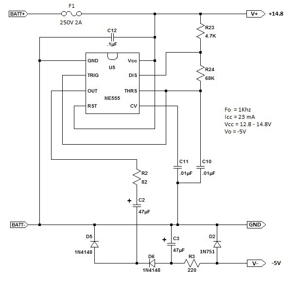
The changes made to the Rectifier Circuit are shown in the schematic above.
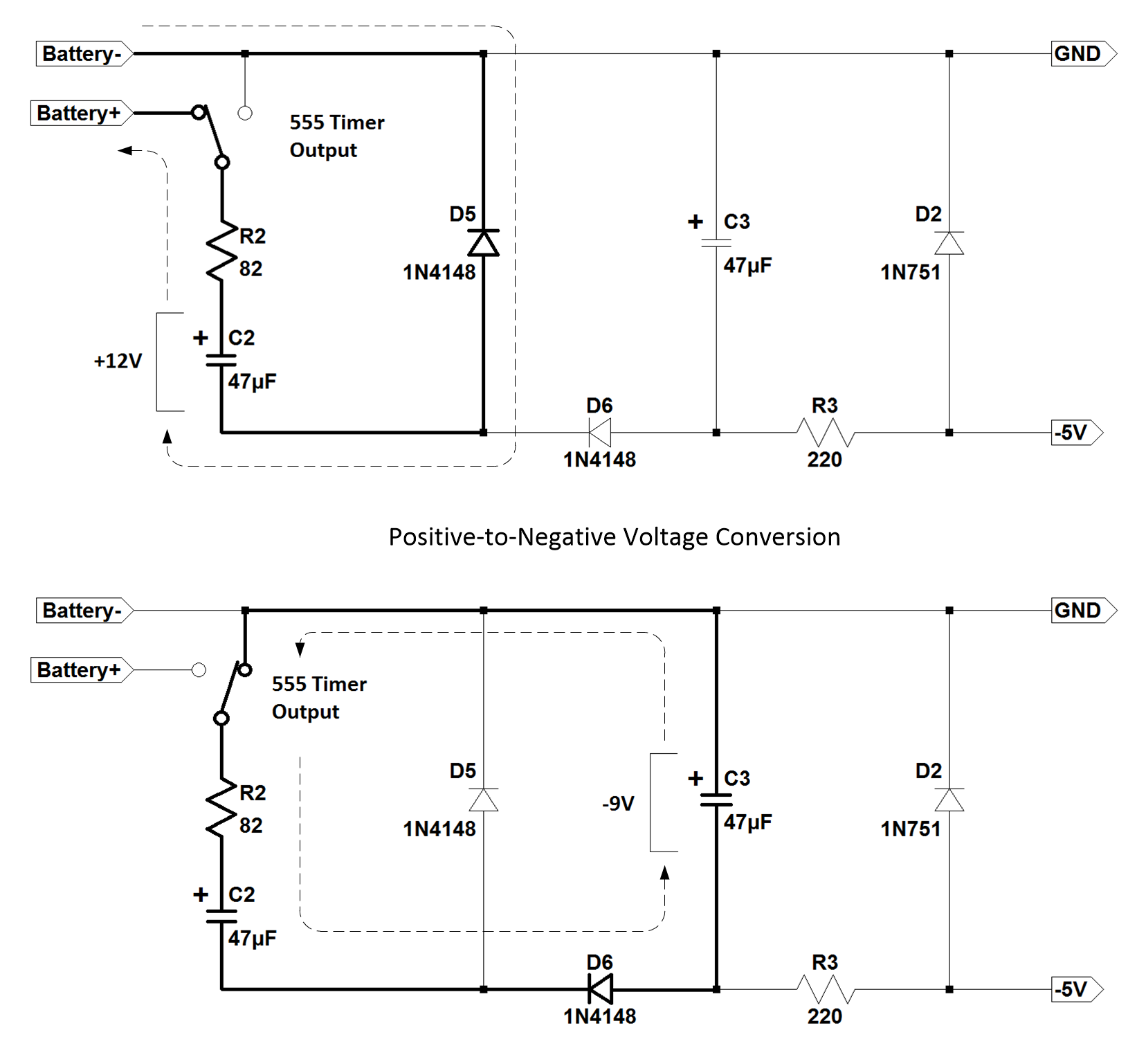
The 555 astable timer is used to replace the positive-to-negative charge switching done by the transformer and bridge rectifier. When the output of the 555 timer is high, capacitor C2 is charged to +12V through diode D5 and resistor R2, while capacitor C3 is discharging into the -5V regulator circuit. When the output of the 555 timer is low, R2 is shorted to ground which reverses the polarity of capacitor C2 and discharges C2 into capacitor C3 through resistor R2 and diode D6. C2 charges C3 to -9V with respect to ground before the cycle repeats. The resulting sawtooth voltage on capacitor C3 is regulated to -5.6V by R3 and Zener diode D2 and sent on to the function blocks that need -5V.
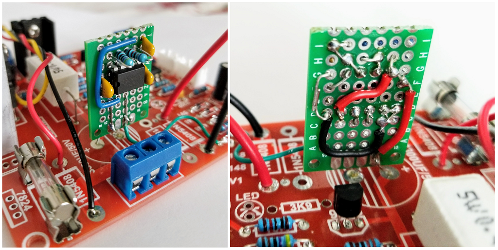
I built the Astable Timer (photos below) on a small piece of prototyping board using the following design procedure:
Most electrolytic capacitor manufacturers provide design data for 60Hz, 120Hz and 1000Hz, so I chose an astable frequency of 1Khz with near 50% duty cycle to minimize the ripple voltage in the converter.
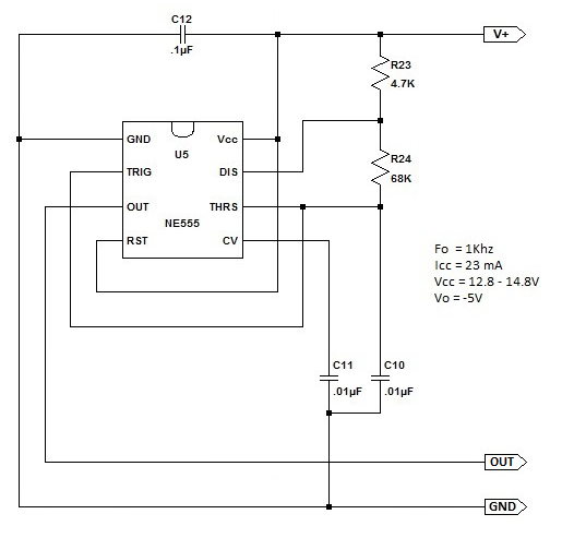
I used the astable circuit from the datasheet and calculated the values for C24, R23 and R24 according to the equations:
T1 = 0.693 * ( R23 + R24 ) * C24 where T1 is the charge time for C24
T2 = 0.693 * R24 * C24 where T2 is the discharge time for C24
F = 1 / ( T1 + T2 ) where F is the astable frequency
DC = R24 / ( R23 + ( 2 * R24 )) where DC is the astable duty cycle
I wanted to keep current consumption on the astable timer low to keep battery drain to a minimum so the combined values of R23 and R24 need to be fairly large. TI includes a nice nomograph that shows the capacitor value needed for a certain frequency and resistor combination. I used that to choose a .01uF value for C24 because the combination of R23/R24 would be near 100K Ohms. Arranging the equation for T1 above to solve for R23/R24 and substituting known values gave:
R23 + R24 = T1 / ( 0.693 * C24) = .0005 / ( 0.693 * .00000001 ) = 72,150 Ohms
The .0005 term for T1 is the cycle time for 1000 Hz (.001 seconds) divided by two for charge time which makes T1 equal to .0005 seconds.
The astable schematic and duty cycle equation shows that a 50% duty cycle requires a large resistor value for R24 and a small resistor value for R23. However, R23 can not be so small that power dissipation in the 555 is exceeded. So I first selected the value for R24 by consulting the EIA E12 resistor chart which describes the most common resistor values I have in inventory, and looked for the resistor value closest to 72,150 Ohms without going over. That value was 68K Ohms. Subtracting 68000 Ohms from 72150 Ohms left 4150 Ohms for R23. Consulting EIA E12 again, I chose the closest resistor value above 4150 Ohms, which was 4.7K, and used that for R23.
Checking the resistor values with the equations shows:
T1 = 0.693 * ( R23 + R24 ) * C24 = 0.693 * ( 4700 + 68000 ) * .00000001 = .000504 seconds
T2 = 0.693 * R24 * C24 = 0.693 * 68000 * .00000001 = .000471 seconds
F = 1 / ( T1 + T2 ) = 1 / ( .000504 + .000471 ) = 1026 Hz
DC = R24 / ( R23 + ( 2 * R24 )) = 68000 / ( 4700 + ( 2 * 68000 )) = 0.48 or 48%
These results are almost perfect for the purpose. C11 and C12 in the schematic are bypass capacitors recommended in the 555 datasheet (attached below).
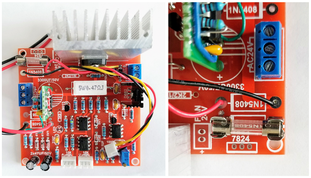
To prevent internal short circuits from damaging the battery, wiring, or circuit board components I recommend installing a Bussman 250V 2A fast acting fuse (5mm X 20mm, Part number GMA-2R) and fuse clips on the PCB as shown above. I used the pads for rectifier D1 to mount the fuse clips. Bussman recommends that the DC voltage applied to their fuses be no more than 1/2 the AC rating, or 125V, to ensure fast clearing of a fault. The maximum battery voltage of 16.8V is well below that. The cold DC resistance of the GMA-2R is 0.066 Ohms which is about the same is an equivalent automotive fuse. If you feel more comfortable using a purely DC rated fuse, feel free to substitute an automotive fuse for the glass fuse I used.
The DROK panel meter will be covered in a later step. The next step will cover the construction and installation of the astable timer.
The LM555 Datasheet is >>> HERE <<<
2. Battery Mod - Astable Timer Construction
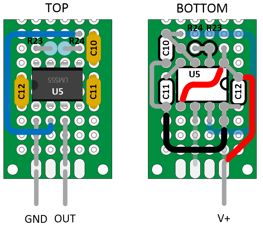
The astable timer I built is constructed on a small piece of prototype board. You can use anything you have on hand and you can use any layout that works for you. Just follow the schematic diagram included above. I've included a top/bottom layout diagram below for the astable timer I built to use as a guide.
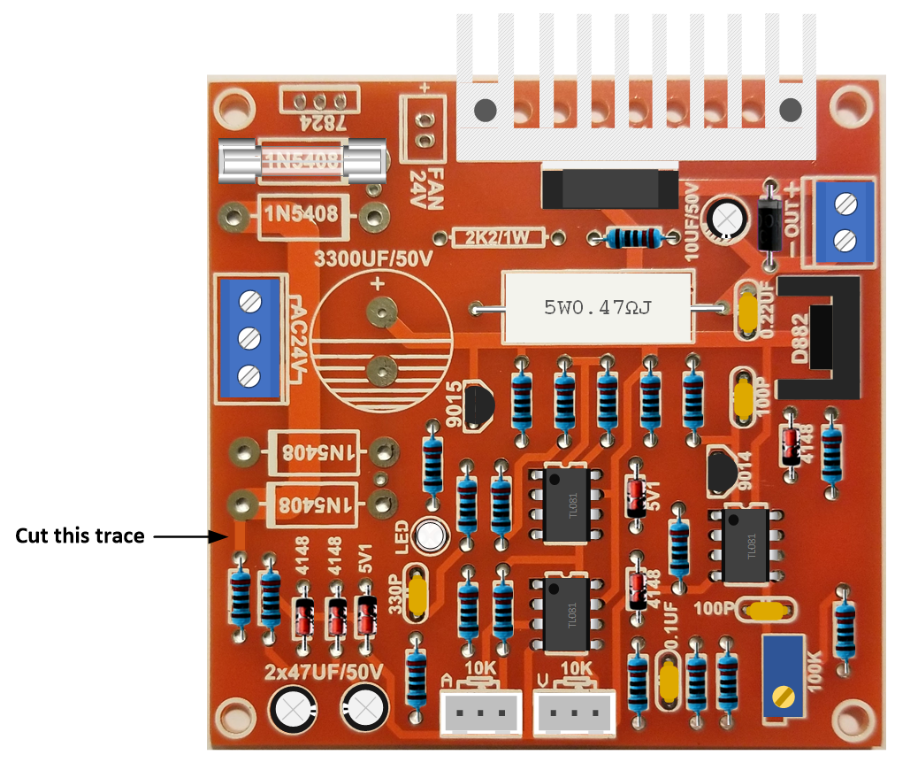
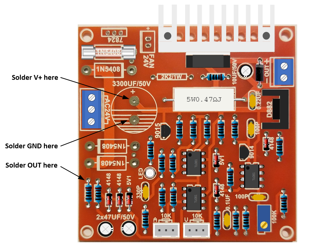
After the astable time is constructed, the trace connecting R2 to rectifier D4 must be cut in the location shown below. Then solder in the astable timer onto the traces indicated below. Small pieces of solid #22 or #24 hookup wire can be used for the V+ and GND leads when the astable timer is installed in the C1 position. But a 2" length of stranded #24 or smaller hookup wire will be needed for the OUT signal to reach R2.
If you aren't planning on attaching a V/I panel meter to the power supply, solder in a #18 or larger jumper wire in the location shown below. Otherwise, install the DROK panel meter before testing the astable timer (see the Multi-Meter Mod in section 6 below).
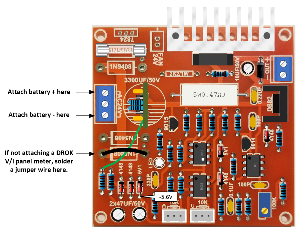
When completed, attach a 12V to 16V power source to J1 as indicated above. Check the voltage at the indicated test point to verify that the timer is working correctly.
3. Battery Mod - Reference Circuit
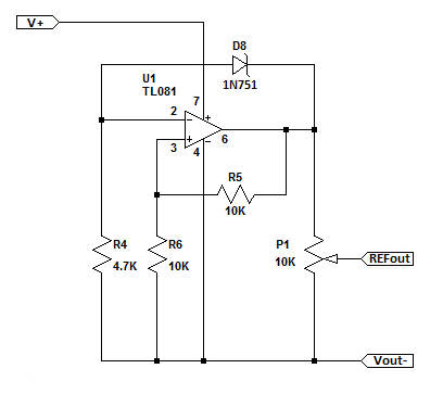
The minimum battery voltage for the 18650 pack I'll be using is 12V. The TL081 OpAmp IC saturation voltage is 1.5V below V+ which is not enough headroom for an 11.2V reference voltage. And I was not convinced that the 5.6V zener was the best choice for temperature compensation. So I elected to replace the 5.6V zener diode included in the WeiKedz kit with a 5.1V zener from my inventory. This will provide a 10.2V reference voltage which is just enough headroom as the battery pack reaches cutoff.
Replace D1 with a 5.1V zener part number 1N751
The 1N751 Datasheet is >>> HERE <<<
4. Battery Mod - Error Amplifier Circuit
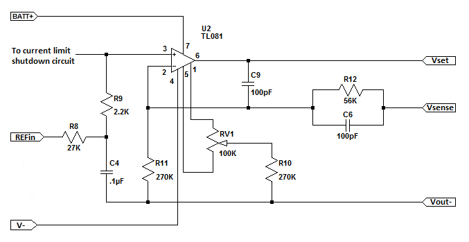
The nominal battery voltage for the 18650 pack I'll be using is 14.8V. Accounting for TL081 saturation voltage (1.5V below V+) and the voltage drop in the power section (1.4V), the maximum output voltage is 11.9V. The gain of the Error Amplifier need to be changed to account for the different V+ voltages (13.8V on battery vs 32.5V on transformer power). Instead of a gain of 3, I needed a gain of:
Acl = Vout / Vref = 12V / 10V = 1.2
The non-inverting amplifier gain equation is:
Acl = 1 + ( R12 / R11 )
To avoid changing the frequency response of the Error Amplifier, resistor R12 should be left at 56K. Rearranging the gain equation to solve for R11:
R11 = R12 / ( Acl - 1 )
Substituting known values makes R11 equal to:
R11 = 56000 / ( 1.2 - 1 ) = 280,000 Ohms
The nearest IEA E12 resistor value is 270K Ohms.
Replace R11 (27K Ohm 1/4W) with a 270K Ohm 1/4W resistor.
For a reference input voltage between 0V and 10V, the power supply output voltage will vary between:
Vout = Acl * Vref
Vout = 1.2 * 0 = 0V
Vout = 1.2 * 10 = 12V
5. Battery Mod - Current Limiter Circuit
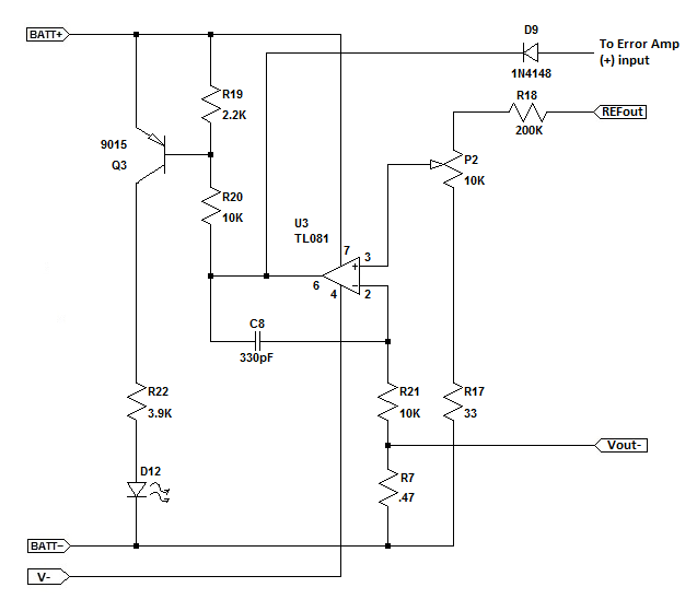
For my purposes I only wanted a maximum of 1A output current. But the current limit control is scaled for 0 to 3A which means that only the first 1/3 of potentiometer rotation would be useful, and if rotated further would allow a higher output current than desired. So the current limit scaling resistor R18 needs to be changed.
The voltage on the current sense resistor R7 depends on the power supply output current. The minimum current limit according to WeiKedz is 4mA and the maximum current for the battery modified power supply is 1A. So the voltage on R7 is:
V = I * R
Vlow = 0.004A * 0.47 Ohms = .002V
Vhigh = 1A * 0.47 Ohms = 0.47V
The output voltage of potentiometer P2 needs to vary between 2mV and 470mV.
If R17 is left at 33 Ohms and the voltage out of the Reference Circuit is 10.2V, then the value of R18 needs to be:
R18 = (( Vref / Vhigh ) - 1 ) * ( R17 + P2 ) = (( 10.2 / 0.47 ) - 1 ) * ( 33 + 10000 ) = 207,704 Ohms
The nearest EIA E12 resistor value is 200K Ohms.
Replace R18 with a 200K Ohm 1/4W resistor.
Using this value to check minimum current limit results in:
Iout = ( Vref * R17 ) / (( R17 + P2 + R18) * R7 )
Iout = ( 10.2 * 33 ) / (( 33 + 10000 + 200000 ) * 0.47 ) = .00034 or 3.4 mA
This is close enough to allow the power supply output current to be varied between 3mA and 1A.
6. Multimeter Mod - Adding a VI Display
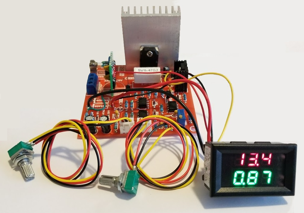
Adding a panel meter to the power supply is a simple matter of soldering in the power, voltage monitor, and current monitor leads at specific pads on the WeiKedz variable power supply PCB. I wanted both a voltage and current display. And I like the look of red/green/blue 7-segment LED's instead of the bland grey of LCD displays, and I didn't want to get too fancy with color LCD meters that measure a whole bunch of parameters. After looking around on Amazon, I liked the DROK V/I DC 0-100V 10A panel meter (Amazon ASIN B00EXCUHJU) best because it has an offset null and span adjustment for current measurements.
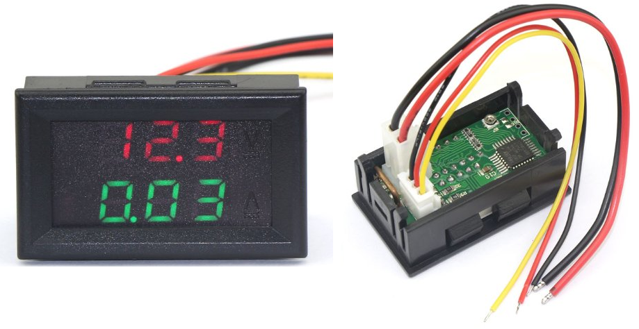
The documentation provided by DROK has not made much sense to me and doesn't appear to be accurate. For example, the documentation for the panel meter I bought suggests that the power leads are isolated from the voltage and current monitor leads. However that is not that case. The meter power ground and current monitor negative lead are internally connected together. And the voltage monitor lead is reference to the power ground lead. So the meter power supply is not electrically isolated from the power supply being monitored as shown in the documentation. Instead, the meter power, load voltage being monitored, and load current being monitored will share the same ground.
As it turns out, though, this panel meter is easy connect to the WeiKedz power supply and works great.
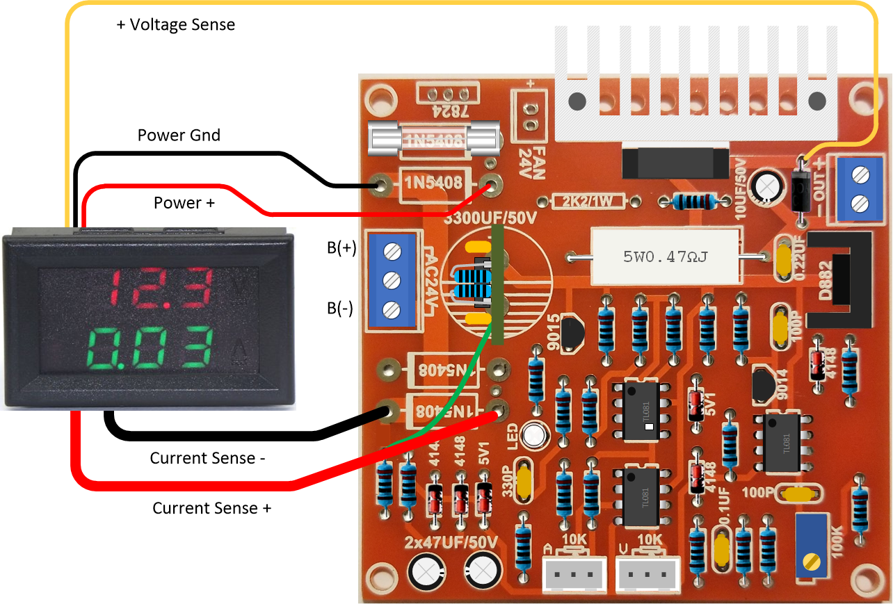
1. Solder the thin red meter lead to the battery + input PCB trace as indicated in the diagram above. The meter + lead will use the unoccupied PCB pad assigned to rectifier D2 cathode.
2. Solder the thin black meter lead to the battery - input PCB trace as indicated in the diagram above. The meter - lead will use the unoccupied PCB pad assigned to rectifier D2 anode.
3. Solder the thin yellow voltage monitor lead to the power supply + output PCB trace as indicated in the diagram above. The voltage monitor lead will be soldered directly to diode D11 cathode.
4. Solder the thick red current monitor + lead to the power supply GND trace as indicated in the diagram above. The current monitor + lead will use the unoccupied PCB pad assigned to rectifier D4 anode.
5. Solder the thick black current monitor - lead to the battery - input PCB trace as indicated in the diagram above. The current monitor - lead will use the unoccupied PCB pad assigned to rectifier D4 cathode.
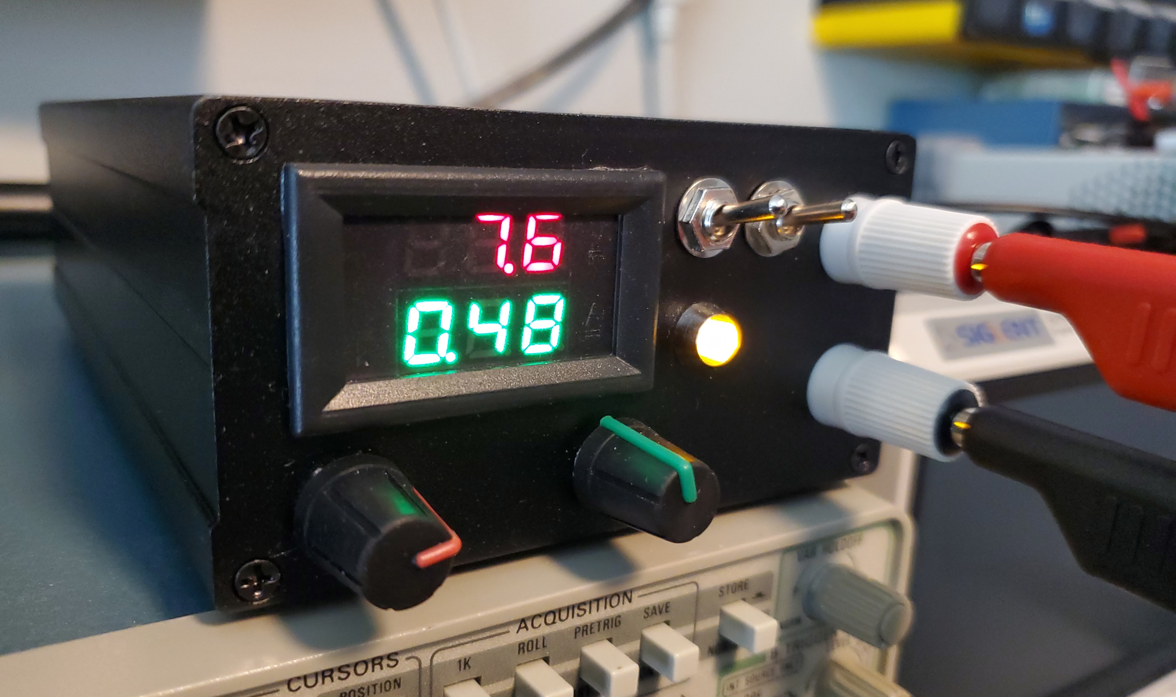
To test, verify that voltage potentiometer P1 is fully counter-clockwise and current potentiometer P2 is fully clockwise. Attach a 10 Ohm 10W load resistor to the power supply output. Attach a 14.8V battery positive lead to the B+ terminal on J1 and the battery negative lead to the B- terminal on J1. The panel meter will power on and display 0V/0A. Slowly rotate the voltage potentiometer clockwise and verify that the voltage and current measurements are close to the following:
Voltage Current
1.00 0.10
2.00 0.20
3.00 0.30
4.00 0.40
5.00 0.50
6.00 0.60
7.00 0.70
8.00 0.80
9.00 0.90
10.00 1.00
The DROK panel meter has a small trimmer resistor on the back that can be used to adjust the current measurement to more closely match the above table if needed.
7. Battery Charger
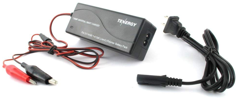
I installed the battery pack in a case with the power supply PCB. To charge the supply without having to disassemble the case each time I purchased a Tenergy TLP4000 Universal Li-ion/Li-Po battery charger from Amazon (ASIN B007MD54NQ). The "protected" cells I used contain their own internal charge/discharge controller so a separate balance circuit wasn't needed. If you use "unprotected" cells, you will need to purchase a balance charge/discharge PCB to avoid unfortunate accidents during use. You can use any battery charger you wish as long as it is designed for the 14.8V pack voltage.
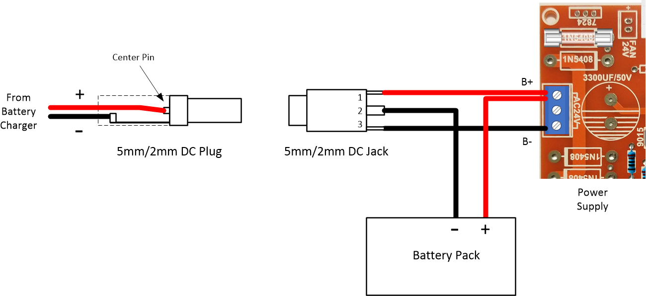
To connect the Tenergy charger to the power supply, I removed the alligator clips provided with the charger and soldered in a 5mm/2mm DC power plug (Mouser 490-PP3-002A) rated at 24VDC and 5A. Then I installed a panel mounted 5mm/2mm DC power jack (Mouser 490-PJ-005A) into the case. The DC input jack is a 3-wire type that disconnects the power supply from the batteries when charging. You can use any DC plug/jack you wish as long as the voltage rating is 24VDC and the current rating is 1A or higher. But be extra careful wiring the charging circuit so that charger, battery, and power supply get connected in the proper polarity is show in the illustration below. Be sure to check the manufacturers datasheet for the DC jack you use to make sure the battery and power supply connections are correct. Pins 1, 2, and 3 are different for each manufacturer. If in doubt, you can verify the pin-out with an Ohm meter. I've included the datasheet for the plug and jack I used below.
The DC Input Plug datasheet is >>> HERE <<<
The DC Input Jack datasheet is >>> HERE <<<
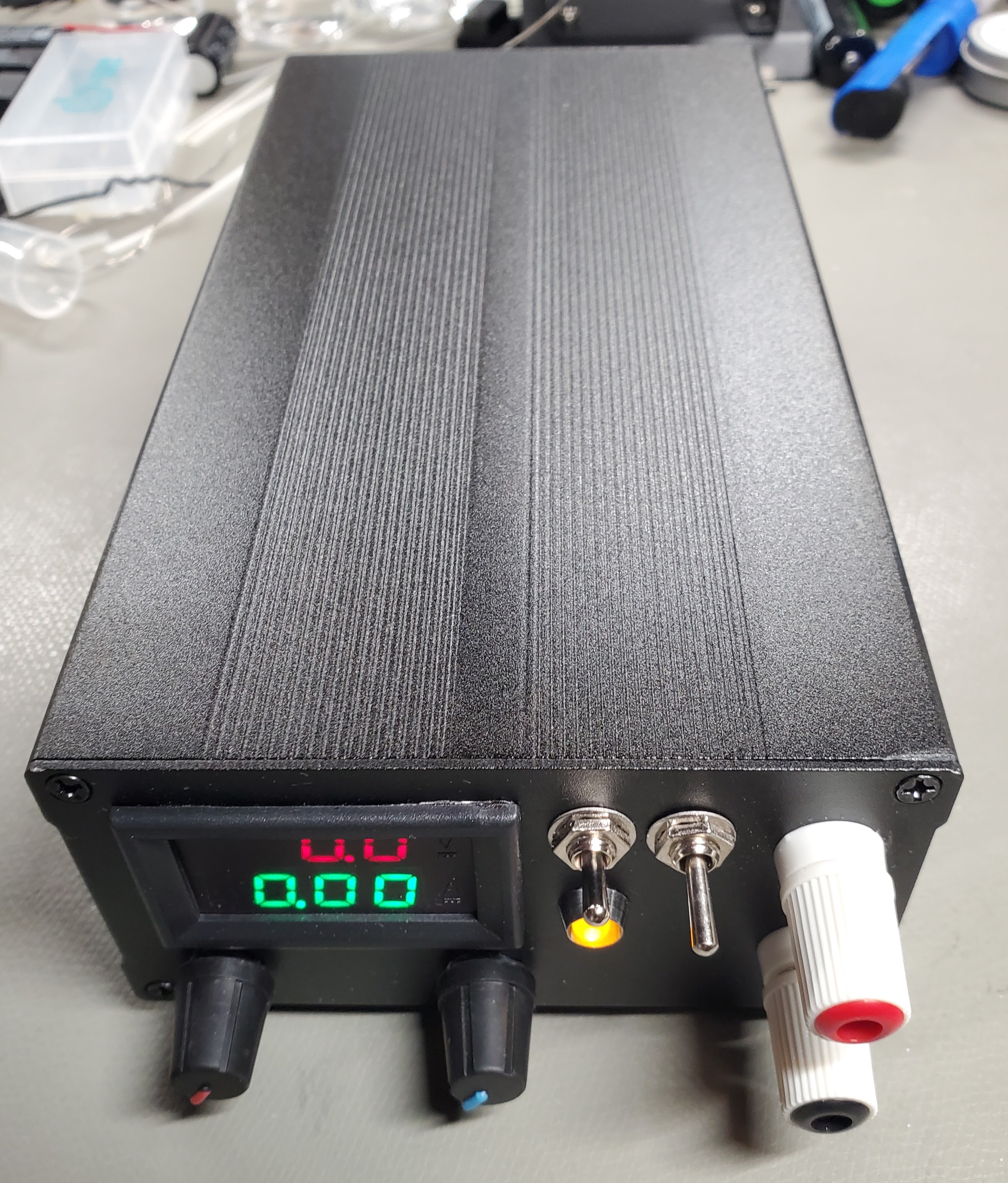
Put it in a case
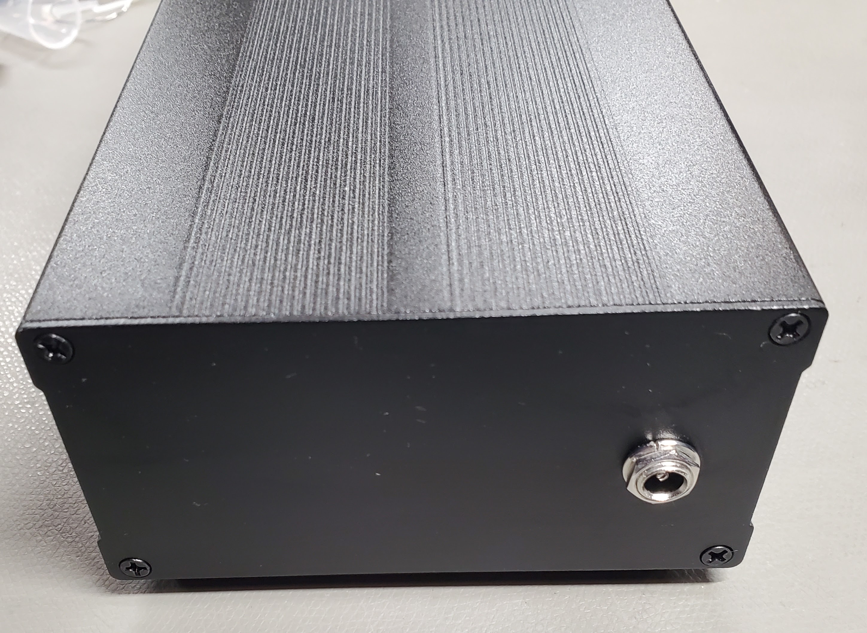
To make the portable power supply really useful it need to be in a safe enclosure. I was interested in a metal case for ruggedness having dimensions that would comfortably fit all the parts without a lot of wasted space. There are many options available on Amazon for not a lot of money. After some careful measurement and review I selected a black anodized aluminum case with dimensions 55mm X 106mm X 200mm. This turned out to be perfect for holding the battery pack, the regulator board, and the front panel controls. You'll find these offered by various sellers so check delivery and pick the best price as there is unlikely to be any difference in materials and finish.

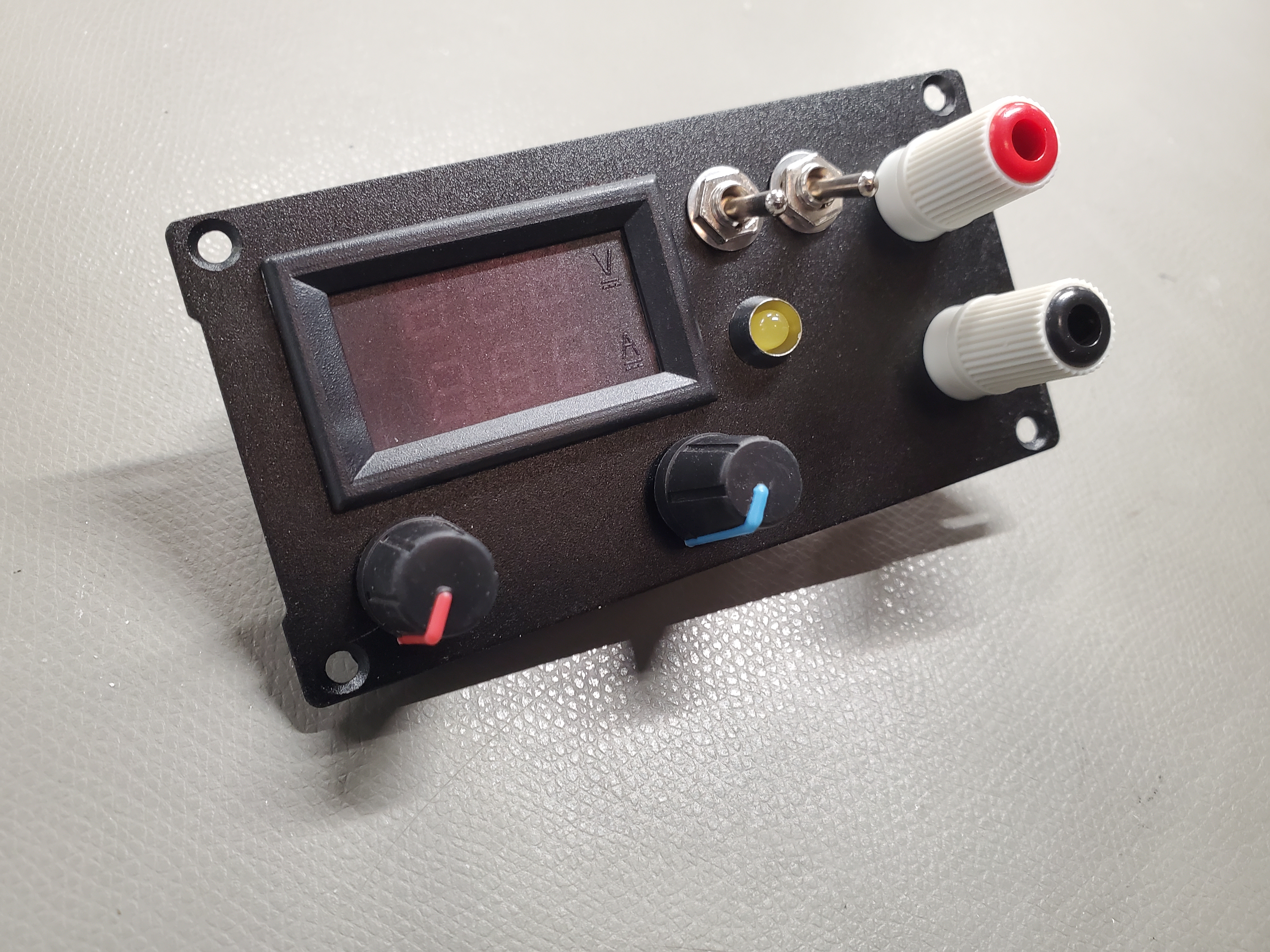
I mounted the V/I display on the front panel and added a battery power switch to turn the power supply on and off. The batteries will be automatically disconnected from the power supply when the charging adapter is inserted but there needs to be a method of disconnecting the batteries when not in use. I decided to add an output power switch so the power supply could be disconnected from the load when needed. And finally I removed the constant current LED from the board and mounted it on the front panel. I think the finished power supply looks very professional and is a welcome addition to my workbench. It has already come in handy on a radio project and a DC-DC converter project where isolation from electrical ground was critical.
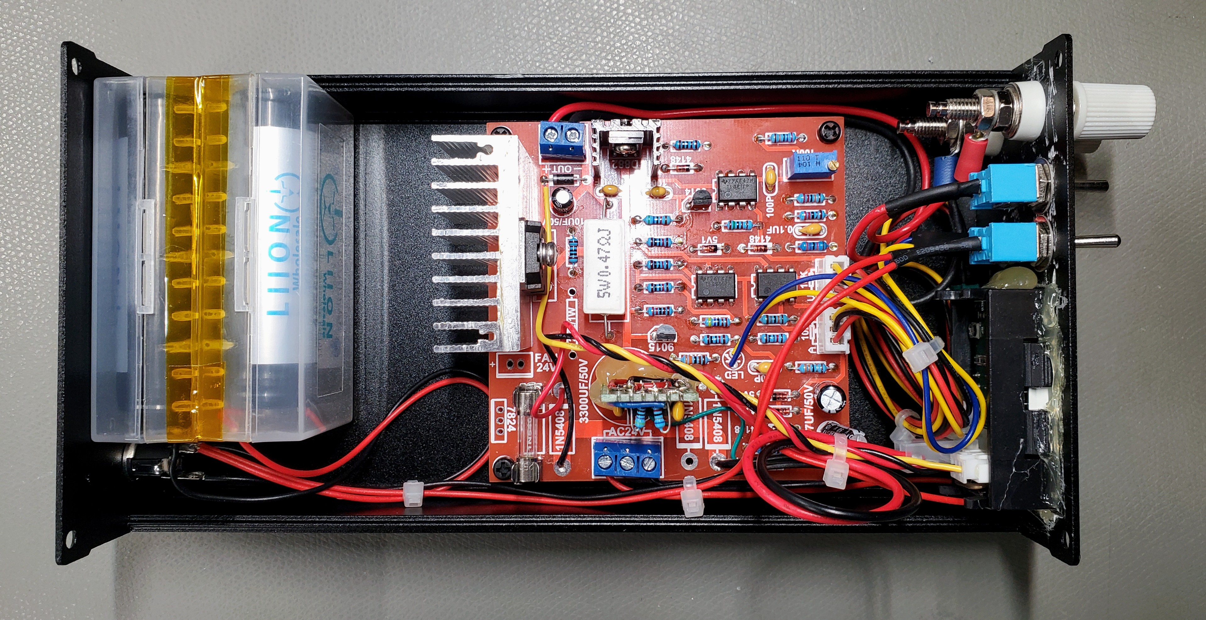
I had to trim down the main heat sink to get it to fit. The heat sink originally provided by WeiKedz was not sufficient for the potential power dissipation when running low-voltage high-current from a transformer. But from a 14.8V battery pack the reduced heat sink will do the job. Some sellers do not include the heat sink so if you get one with your kit be sure to consider it a "suggestion" and do your own thermal resistance calculations to make sure you won't have heating problems in the case you choose. For the battery case, I used the plastic case that Liion Wholesale sent me with the batteries. It came in very handy.
Conclusion
The WeiKedz variable power supply is a good kit that includes a good collection of parts for experimenting, including a large heatsink, fan, and regulator IC. The circuit is well designed and only suffers from voltage and current specifications that are two optimistic. When operated within realistic parameters, the power supply performs extremely well. It comes as a kit which is excellent for hacking. And for $10, the kit is a really good value. I now have a near silent variable power supply that is perfect for sensitive radio and instrumentation circuits. No 120 Hz ripple like you get with a transformer fed power supply. No 70KHz to 100 KHz hash like you get from these cheap switching power supplies. Just clean, smooth, stable DC that's electrically isolated from everything else around.
If you've stuck with me this far, I hope the information presented has been helpful.
Good Luck!
NetZener