Occasionally I encounter a circuit that is schematically simple but challenging in theory, yet has no practical purpose other than to look cool. Every electronics lab needs a black box with blinking lights hanging around in a corner somewhere. Just about every science fiction movie or television show ever made has blinking lights of one type or another. The Neon Goofy Lite project described in this article is easy to build but contains enough interesting parts, theory, and history to start conversations and invite questions from expert and novice alike. The version covered here has been running non-stop making that vintage orange neon glow for over two weeks on four AA batteries.
Between 1968 and 1970, Radio Shack offered 28 project kits designed to introduce customers to breadboard construction techniques and electronics theory. By 1971 there were 26 P-Box kits to choose from and many pages of electronic components, tools, and educational project labs. Unfortunately, after 1974 Radio Shack's preoccupation with Arthur Fiedler, stereo electronics, and CB radio gradually reduced the size of the electronic components and kits section of the catalog. In 1979 there were only six remaining P-Box kits offered and by 1980 they were dropped from the catalog entirely, replaced by printed circuit "kits" that were not as interesting and more than 3 times the cost of the most expensive P-Box project.
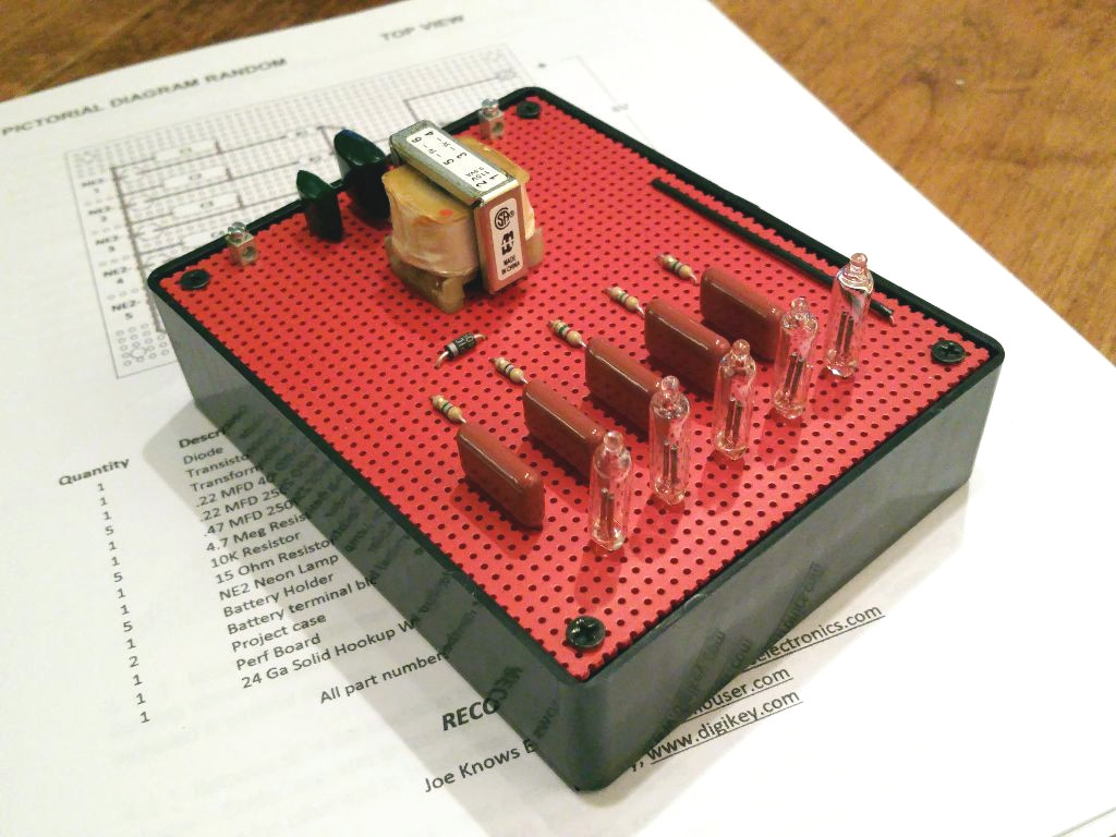
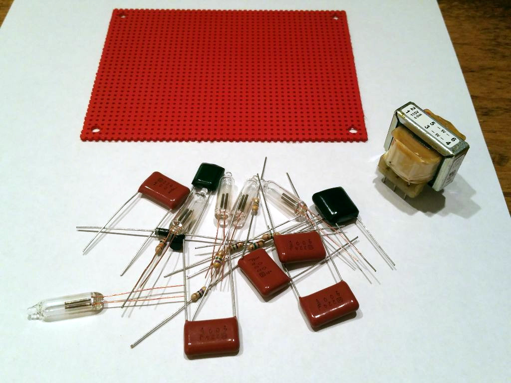
In honor of a great set of educational Radio Shack electronics project kits available during the 60's and 70's, I've redesigned the original Science Fair brand Neon Goofy Lite (Catalog #28-130) using modern components still available from electronics component re-sellers in the US. All of the components in the updated kit can be found at Mouser or Digikey. There were many things Radio Shack did extremely well during its prime. For the nostalgic or the enthusiast who would like to build an updated version of this classic "blinking light" kit, I've included schematics, parts information, assembly documentation, and pictures of a completed and tested Neon Goofy Lite based on the original from 1970.
Obtain The Assembly Manual
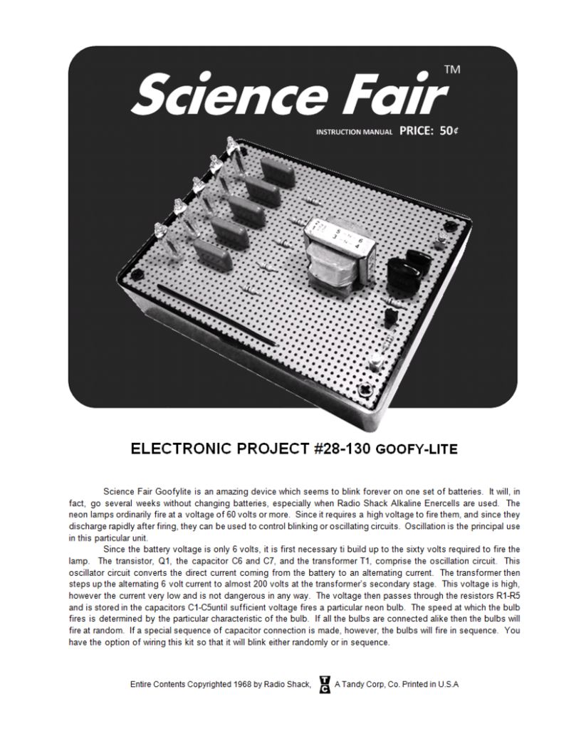
The Neon Goofy Lite project described here is based on the Radio Shack pbox kit of the same name, but it has been updated with silicon transistors and passive components that can be obtained from electronics suppliers like Mouser and Digikey. I've built the updated Neon Goofy Lite kit described here and believe it works just as well as the original kit did back in 1970. To make it easy to replicate my work, I've provided illustrations and step-by-step assembly documentation based on the original assembly manual from Radio Shack.
To build the kit, you will need the revised assembly manual available >>> HERE <<< .
I've kept the original branding and publishing style of the Science Fair Neon Goofy Lite in order to preserve the original look and feel of the documentation set for the builder. But every page has been updated to reflect the changes I've made in order to incorporate modern and available parts.
Obtain Components On The Parts List
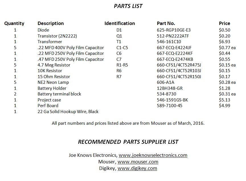
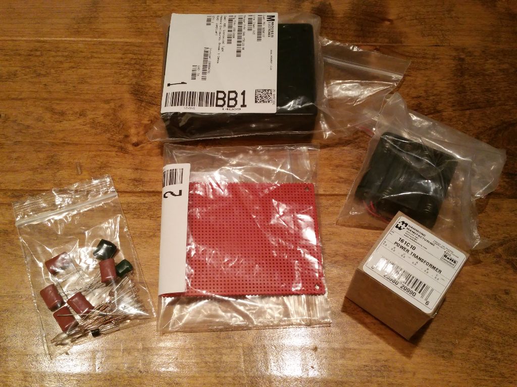
Review the parts list and obtain the components indicated. All components are available from Mouser or Digikey, or can be obtained from other suppliers that may be more convenient to your geography. Total cost is just less than $27. To put that cost in perspective, the Goofy Lite kit was introduced in 1970 at a retail price of $6. The economic value of $6 in 1970 is equivalent to $44 today. The project described in this article can be built for about half the cost of the project kit offered by Radio Shack in 1970. But keep in mind that Radio Shack needed to make a profit from the sale of their kit which explains where the other half of the cost went.
Below are a few notes regarding the parts used for the Goofy Lite project:
1. The resistors for the project can be purchased from Mouser or Radio Shack (assuming they are still in business in your area). But I highly recommend the excellent Joe Knows Electronics resistor kit. It includes the resistors you need for this project and over 860 different values that can be used for other projects, all labeled in individual plastic packages for just $17. For this project you can use 1/4W or 1/2W resistors. It's your choice. Check out www.joeknowselectronics.com. You will not be sorry.
2. The case for the Goofy Lite project I built is a Hammond 1591GSBK ABS Project Box from Mouser. I used a piece of vector breadboard cut to fit on the top and spray painted with high temperature automotive flat red. I like the look of red on black, and the red color of the breadboard matched the red color of the original pbox kit. It's completely up to you how you want to house and color the kit you build.
3. The original pbox kits used tin-plated spring clips for attaching the battery holder to the perf-board enclosure. These clips were a pain to solder to when new and they tarnished like crazy after they were installed resulting in intermittent connections. Fortunately for everyone they are no longer available. I am continuing to experiment with different connector types that are small and inexpensive. For this project I found some small screw connectors from Mouser (part number 534-8730). They aren't perfect but they are very small and make consistently good connections. Feel free to use the battery connector of your choice and let me know if you find something that works really well for you.
4. The original pbox kit used an audio coupling transformer for T1. This coupling transformer is no longer available from the original manufacturer or any alternative source I could find. Fortunately it was quite easy to find a suitable replacement transformer of equivalent turns ratio from Hammond Power Solutions (Mouser Part 546-161C10). This transformer is roughly twice the size of the original Radio Shack transformer but performs much better in my opinion. The only disadvantage is that the Hammond transformer core doesn't whine like the old audio transformer used to. It's very effective but completely silent.
5. Pay particular attention to the voltage rating of the capacitors. This project generates up to 130V DC on the T1 secondary in order to ionize the neon gas in the lamps. Don't use capacitors less than 200V DC for C1 through C5.
CAUTION: Although the current generated by T1 is extremely low and considered harmless, don't go out of your way to touch components on the high voltage side of the circuit when it is running. Don't take this circuit with you to the tub to see if it will float while you are taking a bath. Don't try to shock your friends with it. Treat all electronic circuits with the respect they deserve.
Please Note: I have no business relationship with any of the above vendors. Nothing of financial value was exchanged for my recommendation. None of the above vendors provided compensation of any kind during the creation of this project. I will not be compensated in any way if you choose to build this project or purchase components from any vendor I recommend. I simply had a good experience with the vendors I recommend and believe you will too.
Review the Schematic to Become Familiar With the Goofy Lite Design
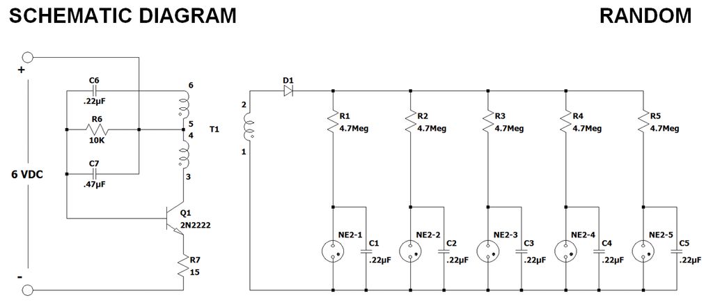
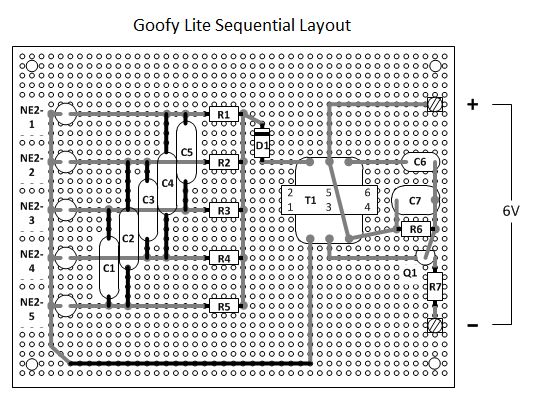
You have a decision to make, which is actually pretty cool since most projects can only be constructed one way and can only do one thing. But the Neon Goofy Lite project is more flexible than that. It is possible to configure the project to flash the 5 neon lamps in a pseudo-random pattern or a sequential pattern. I built both circuit types and liked the pseudo-random pattern the best (see the video on the summary page) but your preference may be different from mine. The assembly manual covers both types in detail so it's entirely up to you which circuit you build.
The Goofy Lite circuit looks simple but contains enough theory to keep a second year engineering student busy. The core of the circuit is a negative resistance device: The NE2 neon lamp (also known as the A1A lamp). There aren't many devices in electronics that exhibit negative resistance; a few microwave diodes, SCRs, the uni-junction transistor, and gas discharge tubes like the neon lamp. The great thing about a negative resistance device is that it can be used to build a simple oscillator with only a couple of passive components. No amplifiers or feedback networks required.
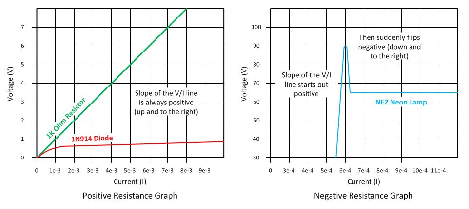
Negative Resistance
To get an idea of what is meant by "negative resistance", review the two V/I charts below. The first represents a V/I graph of a diode and a resistor, both positive resistance devices you are probably already familiar with. The second represents the V/I graph of a neon lamp, a negative resistance device. Notice in the positive resistance graph that the slope of the V/I curve is always positive (up and to the right). Increasing current through the device always results in an increasing voltage drop across the device. However, notice that the neon lamp has a portion of its V/I curve with a negative slope at the lamp breakdown voltage (90 volts). In the negative slope region, increasing current through the lamp results in a decreasing voltage across the lamp. This characteristic is what makes the blinking neon lamp in the Goofy Lite project possible.
In the 50's and 60's, neon lamps were used to build all sorts of interesting circuits including oscillators, timers, binary counters, binary dividers, lamp dimmers, and light detectors. The only disadvantage with neon lamps today is their high voltage requirement (60V to 150V). But in the past, these voltages were common for electron tube (valve) circuits making it very easy to use a neon lamp. Review the two neon lamp circuit diagrams below. One is a Relaxation Oscillator circuit and the other is a Multivibrator circuit. The Relaxation Oscillator is used in the Random version of the Goofy Lite project. The Multivibrator is used in the Sequential version of the Goofy Lite project. Below is a description of how each circuit works:
Neon Lamp Relaxation Oscillator
In order to control the flash rate of the neon lamp, we need a time delay. A simple time delay circuit can be constructed with a resistor and a capacitor in series, often referred to as an RC circuit. When energized, the capacitor gradually charges to near the power supply voltage. How quickly the capacitor charges is determined by the value of the resistor and the value of the capacitor according to the following formula:
Trc = R * C
Refer to the Relaxation Oscillator Schematic below. When power as applied to the series circuit C1/R1, capacitor C1 will begin to charge. When C1 voltage reaches the neon lamp firing voltage (90V), the neon lamp will light and C1 will discharge into the neon lamp. Resistor R1 will essentially be isolated from the circuit due to the relatively low resistance of the neon lamp. When C1 voltage falls below the neon lamp holding voltage (50V), the neon lamp will extinguish and C1 will begin charging again through R1. This cycle will repeat for as long as power is applied to the circuit.
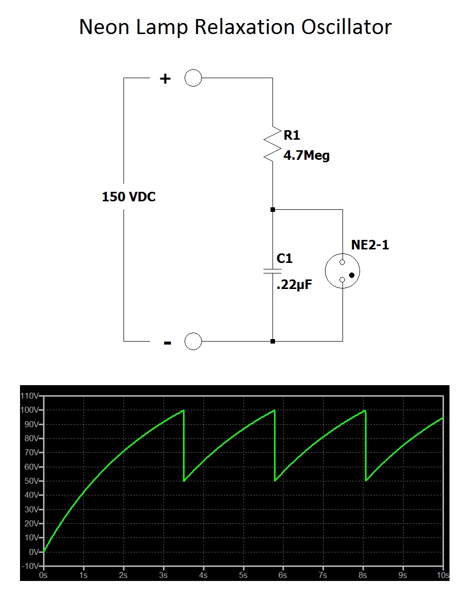
Review the chart underneath the Relaxation Oscillator Schematic. The chart contains the capacitor voltage over time. Notice that the capacitor does not charge in a straight line but in an exponential curve function. The equation for this curve is:
Vcapacitor = Vpower * [ 1 - e^(-t/RC)]
You might recognize this equation if you've had a class in statistics, physics, or calculus. This equation is very easy to use with a modern calculator so don't let it intimidate you. Solving the equation for the resistor and capacitor values RC will render it a little more useful when designing circuits like the Goofy Lite:
RC = -t / ln (( Vf - Vh ) / Vf )
In the above equation, ln is the natural log function on a calculator, Vf is the neon lamp firing voltage, Vh is the neon lamp holding voltage, t is the desired lamp flash rate, and RC is the product of the capacitor and resistor needed to produce a flash rate of time t.
For example, I wanted a flash rate around 1 second for each lamp so I used the following:
Lamp Firing Voltage = 90 VDC
Lamp Hold Voltage = 50 VDC
RC = -1 / ln (( 90 - 50 ) / 90 ) = 1.23
I wanted to keep the .22uF capacitor values used by the original P-Box kit, so all I needed to do was divide the RC value by .00000022 Farads in order to obtain the value for the resistor:
R = 1.23 / .00000022 = 5.5 Megohms
The nearest standard resistor value I had in inventory was 4.7 Megohms so I used that for the resistor values in the random circuit.
The reason this circuit is referred to as "Random" is that the flash rate for each neon lamp will vary depending on the tolerance of the capacitors, resistors, and lamps. Many capacitors have a tolerance of 10% and 20%. The resistors I used were 5% tolerance. The neon lamps seem to have firing and hold voltages that varies as much as 20%. All of these tolerances combined will vary the actual neon lamp flash rate between .8 seconds and 1.2 seconds. Sometimes more. This results in what appears to the eye to be a random flash pattern among the 5 neon lamps. If you focus on one lamp you will see that the flash rate is actually fixed for that lamp. The other lamps are firing at different rates which creates the illusion of a random flash pattern.
Neon Lamp Sequential Multivibrator
All of the principles described above apply to the sequential circuit. The only difference is where the capacitors are attached. The sequential version of the Goofy Lite is composed of several Multivibrator circuits distributed among the 5 neon lamps. Review the sequential circuit diagram below and the chart attached to it.
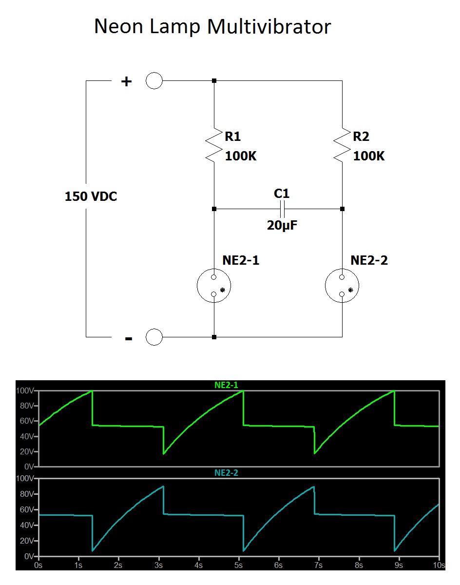
When power is applied, one of the neon lamps will immediately fire first due to manufacturing tolerances. In this description, lets assume that neon lamp NE2-1 fires first. When NE2-1 fires, it creates a conductive path for capacitor C1 to charge. When the voltage on C1 reaches the firing voltage of NE2-2, that lamp will fire which causes the voltage on C1 to extinguish neon lamp NE2-1. C1 will then charge through the conductive path provided by NE2-2 until it approaches the firing voltage of NE2-1. NE2-1 will then fire causing the voltage on C1 to extinguish neon lamp NE2-2. This cycle will repeat for as long as power is applied to the circuit.
By carefully distributing three copies of the Multivibrator circuit among the 5 neon lamps, the sequential circuit can be made to flash each neon lamp one after the other.
DC-DC Step-Up Converter
If all the above theory wasn't enough, we still need some way of producing 150V DC from a set of AA batteries. The original P-Box kit used an audio transformer with a 24:1 turns ratio to step up the 6 VDC battery voltage to around 150 VDC for the neon lamps. However that audio transformer is no longer available from any commercial source (I've tried them all). Occasionally someone on eBay will offer one for sale from an estate auction, but you can't buy these in volume from any commercial company. An acceptable solution to this problem turns out to be very simple. Any step-down power transformer can be used as a step-up power transformer when the primary and secondary windings are transposed. All I needed to do was find the smallest step-down power transformer commercially available that provided a turns ratio of around 24:1. It turns out that Hammond Power Solutions makes a small transformer with a 115V primary and dual 5V secondaries which is just perfect for the Goofy Lite project. The Hammond transformer is about twice the size of the original Radio Shack audio transformer but is still quite small and performs extremely well as a substitute.
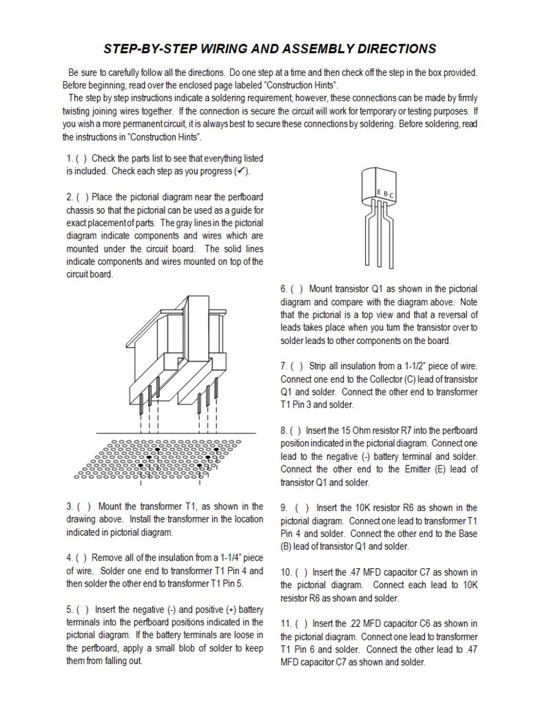
The DC-DC Step-Up Converter is actually a classic Blocking oscillator which uses a tapped primary inductor for the energizing and feedback circuits. All I needed to do was connect the Hammond transformer secondary coils together so that they appeared to Q1 as a tapped inductor. R6 is a current limit for the base of Q1 while C7 ensures that the base of Q1 gets a "kick" when power is first applied to ensure that the DC-DC converter circuit starts oscillating. The second secondary winding of T1 provides the positive feedback signal to Q1 which keeps the DC-DC converter circuit oscillating. C6 isolates the feedback winding of T1 from the 6V battery so that only the feedback signal controls the operation of Q1.
When power is first applied, the base of Q1 will be tied briefly to V+ which immediately saturates Q1 and starts current flowing through the first secondary winding of T1. Feedback from the second secondary winding will begin to reverse bias Q1 resulting in less current through the first secondary winding. When Q1 becomes turned off, the combination of R6/C7 will begin turning Q1 back on again and the entire cycle will repeat as long as power is applied. The frequency of oscillation for the converter is around 135Hz.
The number of wire turns in the primary coil of T1 are 23 times higher than the number of turns in the secondary coils. This multiplies the voltage applied to the secondary coils attached to Q1 by 23 resulting in a voltage to the neon lamps of approximately:
Vsecondary * Turns_Ratio = Vprimary
6 VDC * 23 = 138 VDC
This is more than enough to run both the random and sequential versions of the project. Average current consumption is 18mA so a set of four AA batteries should run at least two weeks non-stop.
Hopefully this section has helped you understand how the Goofy Lite circuit was designed and how it operates.
Review the Circuit Board Layout
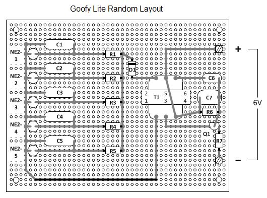
The Assembly Manual provides a step-by-step checklist for installing and soldering each component to the vector board. As you can see from the opposite side illustration of the vector board, I've used point-to-point wiring with 22 AWG solid hookup wire. Most of the connections can be made with just the component leads. But power, ground, and signal bus leads are best done with lengths of hookup wire. There are two versions of the Goofy Lite project. I've built the Random version and illustrated the opposite side of the circuit board. The sequential version will be very similar.
When it comes to wiring, try to be as neat as I've indicated in the assembly manual. You don't have to be the world's best soldering artist but there's no good reason to do the work half-way. Go all out and make your project look as good as you can.
Follow the Steps in the Assembly Manual to Complete the Goofy Lite Project
Before you begin:
The perfboard specified in the parts list is too large to fit onto the Hammond case so some trimming is required as indicated in the images below. Follow the steps below to prepare the perfboard before installing components:
1. Using a sharp edge, carefully score the perfboard along the TOP ROW and BOTTOM ROW row of holes all the way to the end of the board. Run the sharp edge over the score line several times until it penetrates 1/4 to 1/2 way through the perfboard.
2. Using a sharp edge, carefully score the perfboard along the RIGHT COLUMN and LEFT COLUMN of holes all the way to the end of the board. Run the sharp edge over the score line several times until it penetrates 1/4 to 1/2 way through the perfboard.
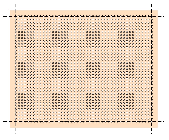
Score edges of perfboard along dashed lines
3. Using a small pair of pliers, carefully bend the TOP ROW section back away from the score line. Work with one end of the TOP ROW, moving to the center, and then the other end. The TOP ROW section will eventually break away from the perfboard.
4. Using a small pair of pliers, carefully bend the BOTTOM ROW section back away from the score line. Work with one end of the BOTTOM ROW, moving to the center, and then the other end. The BOTTOM ROW section will eventually break away from the perfboard.
5. Using a small pair of pliers, carefully bend the RIGHT COLUMN section back away from the score line. Work with one end of the RIGHT COLUMN, moving to the center, and then the other end. The RIGHT COLUMN section will eventually break away from the perfboard.
6. Using a small pair of pliers, carefully bend the LEFT COLUMN section back away from the score line. Work with one end of the LEFT COLUMN, moving to the center, and then the other end. The COLUMN section will eventually break away from the perfboard.
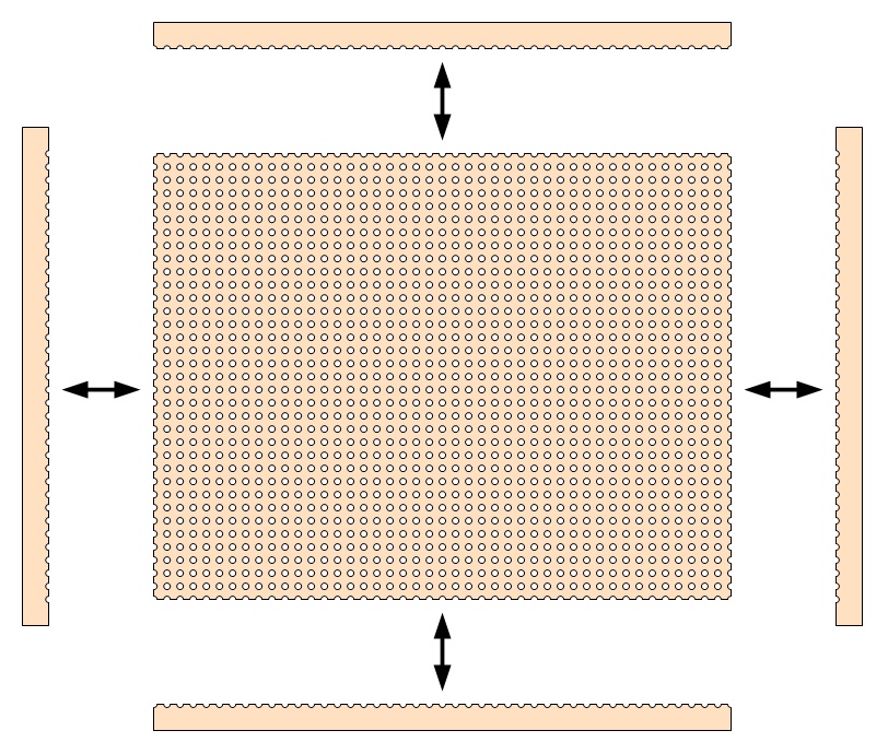
Carefully break apart perfboard edges along score lines
7. Using an Exacto knife, match the trimmed perfboard with the Hammond case and enlarge holes at the corner to match with the corner mounting holes in the case. Work slowly and carefully with minimal pressure to avoid breaking the corner piece.
8. Place the potentiometer mounting brackets onto the perfboard and enlarge holes in the perfboard to match the holes in the brackets. Work slowly and carefully with minimal pressure to avoid cracking the perfboard.
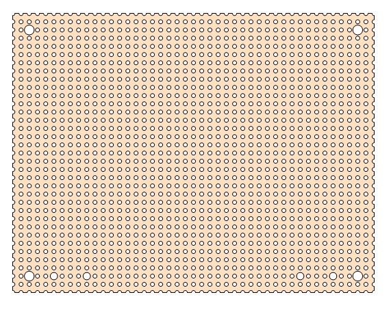
Cut holes for case and bracket screws
9. Spray paint the perfboard with the color of your choice or leave it natural. It's your choice.
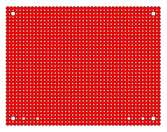
Paint with desired color
I typically use flat red followed up with 2 to 3 coats of gloss clear, but feel free to use any color that you like best.
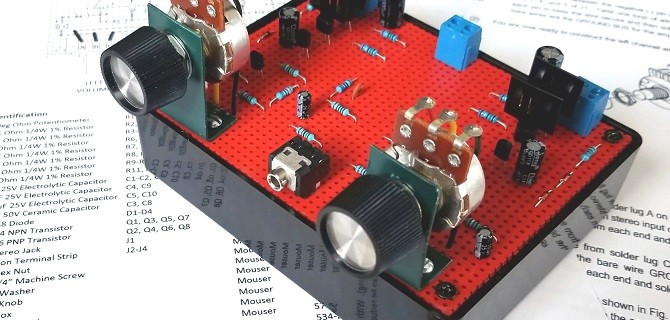
Assembly Photos - DC/DC Step-Up Converter
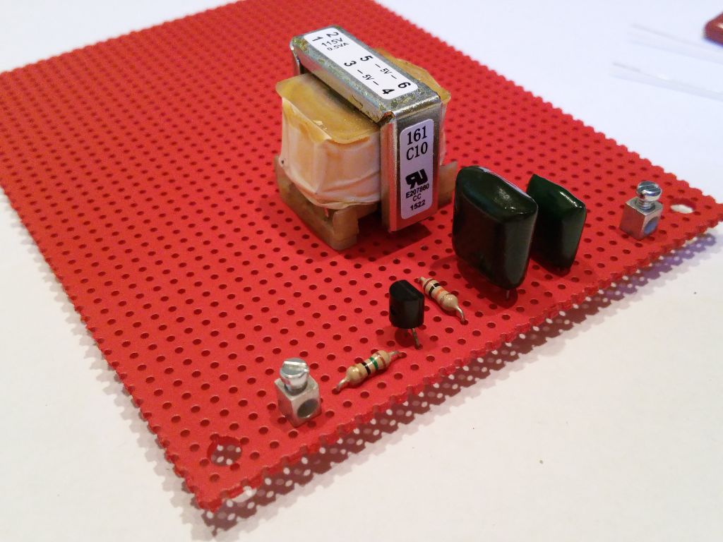
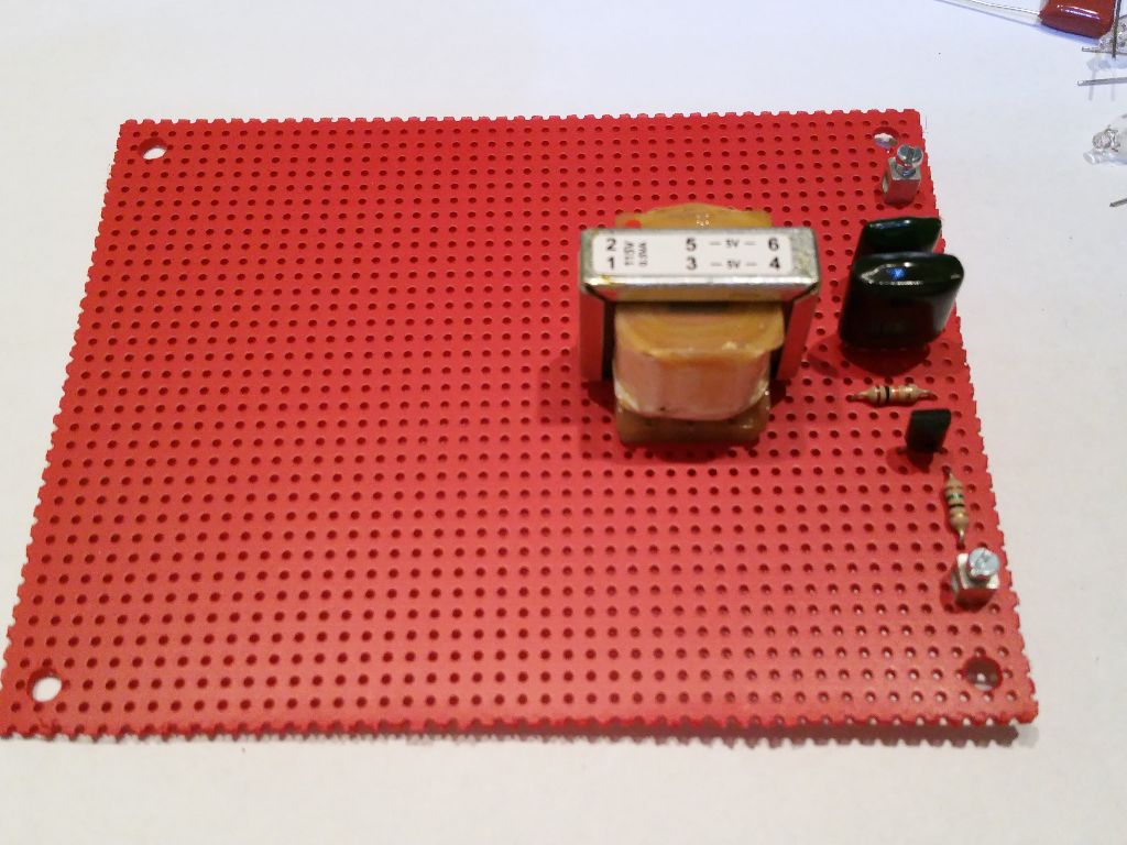
After Step 12 in the Assembly Document, the Goofy Lite project should look something like the photos above.
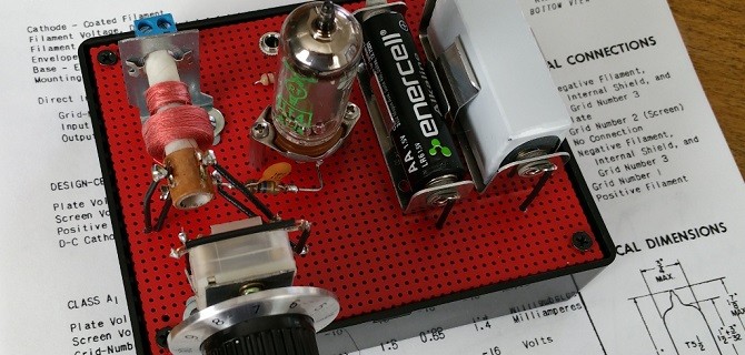
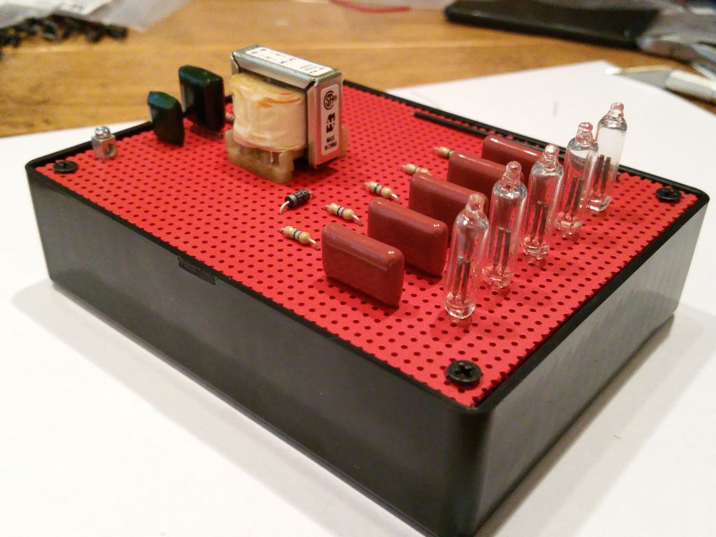
Assembly Photos - Neon Lamp Section
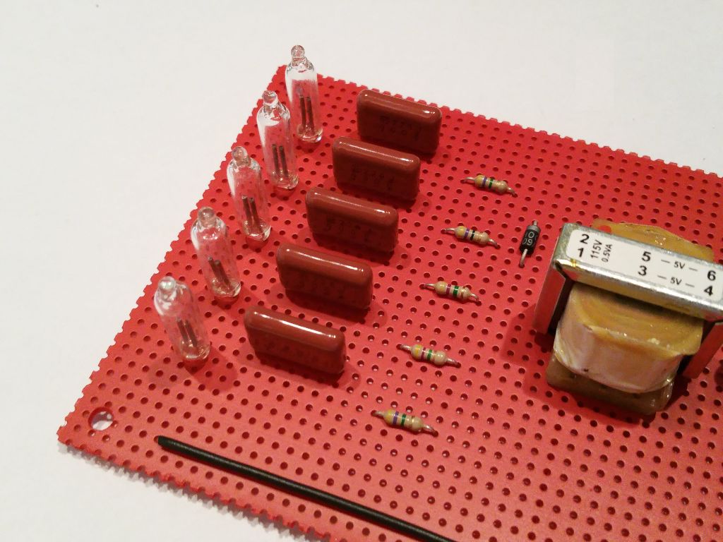
After Step 28 in the Assembly Document, the Goofy Lite project should look something like the photos above.
Note: Capacitors C1 through C7 will be in a different location depending on the version of the project that you build. What is shown is the Random layout.
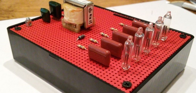
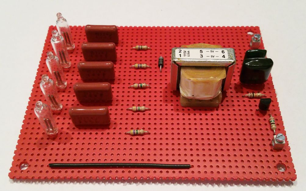
Assembly Photos - the Completed Goofy Lite Project
When completed and powered up, the Neon Goofy Lite project will operate non-stop for weeks at a time. It's a great conversation starter when you have visitors in the lab. And it's an easy to build weekend project that you can do with a family member. Young people are amazed at the voltages that can be generated and used with a few 1.5 volt batteries, and the flash of orange glow from small neon tubes is almost hypnotic.
This revival of a vintage tech project has worked very well for me. Those that have wanted to build a Radio Shack Goofy Lite project but were thwarted due to the lack of a suitable transformer can now proceed with confidence. This was a fun project for me. I hope it is also fun and interesting for you.