Introduction
While doing some research on the transition to solid state devices I encountered a really interesting article on the worlds first Transistorized Hi-Fi System. This article provides a nice back-stage view on how electronic design is carried out. Often, success depends on convincing your boss that a certain idea or process is worthwhile. Transistors in the 50s were hard to manufacture, noisy and unreliable, and when they worked it was only at low frequency and very low power. Many engineers were struggling to figure out what the transistor was good for outside of miniature hearing aids or signal conditioning in diode logic circuits. Sure the vacuum tube was large and inefficient, but it could do just about anything that needed doing at the time. Except when you needed thousands of them for a computer, then they weren't so great.
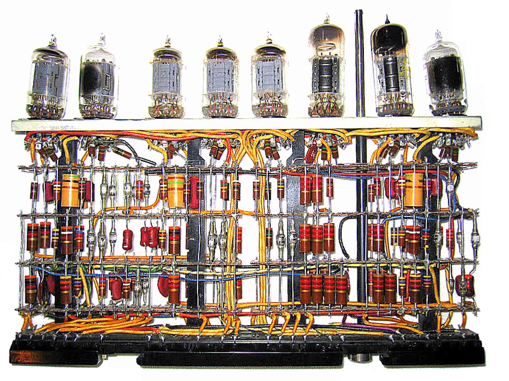
IBM 700 Series Logic Module
By the 1960s, the transistor had finally found it's niche in portable and mobile AM radios, Hi-Fi stereo systems, computers, and telephone repeaters while vacuum tubes continued to carry the day in high frequency radios, RF power amplifiers, and high voltage switches. The transistor had to pick it's battles against the vacuum tube while new materials and manufacturing processes were being developed. Far from an explosion, the shift to transistors and the obsolescence of the vacuum tube required decades. The CRT display, a giant glass vacuum bottle filled with tin, copper, zinc, cesium, silver, and lead didn't leave the scene until the first decade of the 21st century, replaced by a flat glass screen full of transistors. But we still have vacuum tubes in our microwave ovens. Last stand, I guess.
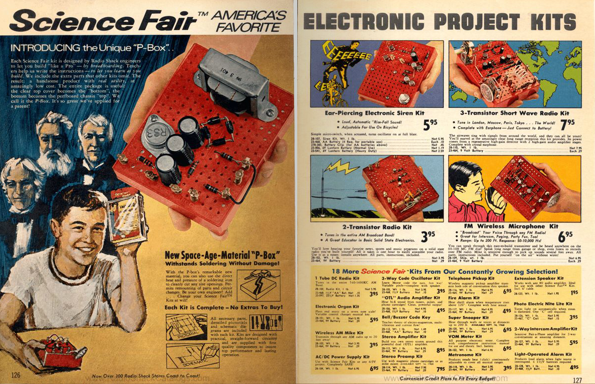
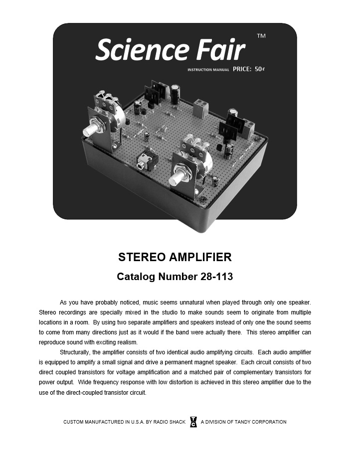
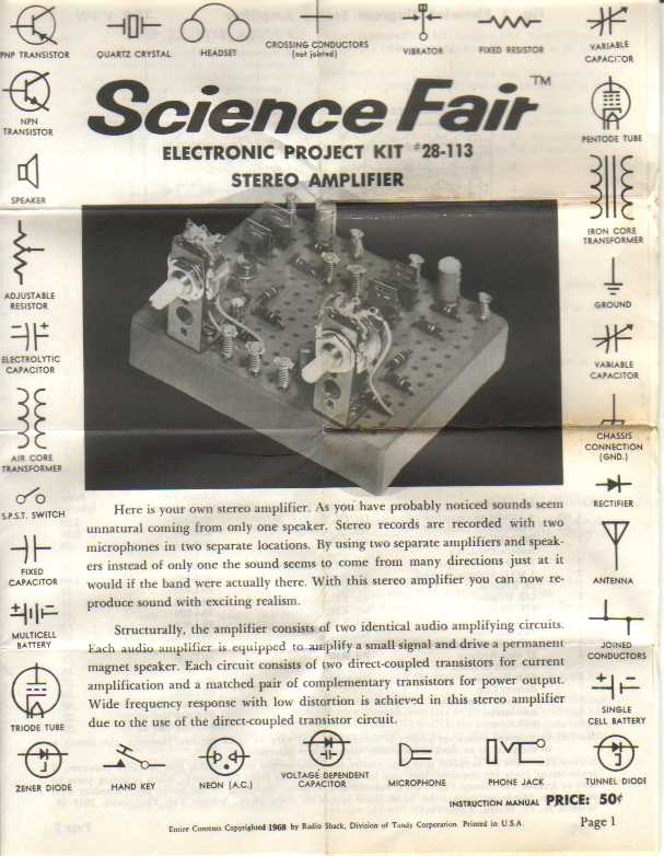
Science Fair PBox Kits
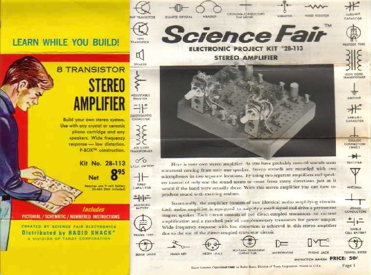
In 1968, Radio Shack introduced it's first P-Box kits marketed to the electronics experimenter. These were great kits containing all the electronic components, wire, and perfboard needed to build a useful electronic device. The first P-Box kits released in 1968 looked suspiciously like those sold by Eico under the Eicocraft brand but quickly expanded (Radio Shack sold experimenter kits from Eico, Knight, and Allied Radio until 1973). In 1969, an 8 Transistor Stereo Amplifier kit was released but withdrawn in 1972. The reasons are unclear, but I suspect the germanium "matched pair" transistors were expensive and hard to source. In addition, the amplifier kit was one of the most complex in the catalog and probably didn't work very well which would have been disappointing given it's cost.
After reading the transistorized Hi-Fi article referred to earlier and reviewing the available documentation on the 8 Transistor Stereo Amplifier kit, I wanted to build one. Most cheap amplifiers in 1969 used at least two coupling transformers. These transformers simplified the amplifier circuit but they added weight and limited low and high frequency response. The Radio Shack kit used a push-pull direct coupled design, found only in "serious" Hi-Fi equipment at the time which eliminated the transformers. All I needed to do was redesign the kit for silicon transistors, improve the push-pull bias circuit, and limit high frequency response to something reasonable. The result of that work is the subject of this article. I was very pleased to have ended up with a nice little "vintage" amplifier that produces room filling sound when connected to an efficient speaker system. As you can tell from the video demonstration at the beginning of this article, you don't need 1000W at .00000001% THD to fill a room with good tunes.
The specifications I obtained from the amplifier I built were:
THD: <1% at 500mW per channel
Input Impedance: 700K Ohms minimum
Sensitivity: -10dbV (0.316 Vrms) see note below
Frequency Response: 35Hz to 20Khz (+/- 1db)
Cutoff Frequencies: 27 Hz and 65 Khz
Input Power: 9V @ 500mA max, or 12V @ 700mA max. 1000mA recommended.
Output Power @ 9V Input Power: 1W into 8 Ohms (0.5W per channel) or 2W into 4 Ohms (1W per channel)
Output Power @ 12V Input Power: 2W into 8 Ohms (1W per channel) or 4W into 4 Ohms (2W per channel)
Note: The input sensitivity of the amplifier is scaled to consumer line level input voltages of about 0.8Vpp (0.316Vrms) for maximum output power. Although this is perfect for a Laptop, MP3 player, mixer, CD player, AM/FM tuner, or vintage tape deck, it may not be sufficient for many acoustic/electric instrument pickups or dynamic microphones without a pre-amplifier or "stomp-box".
ALSO...
Be sure to check out the assembly manual further down the page because it includes several suggestions for improving the amplifier by:
- Adding an LED Power Indicator
- Doubling the output power to 2 Watts
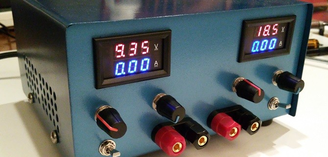
- Adding an AC power supply for both home and portable operation
- And more...
How It Works
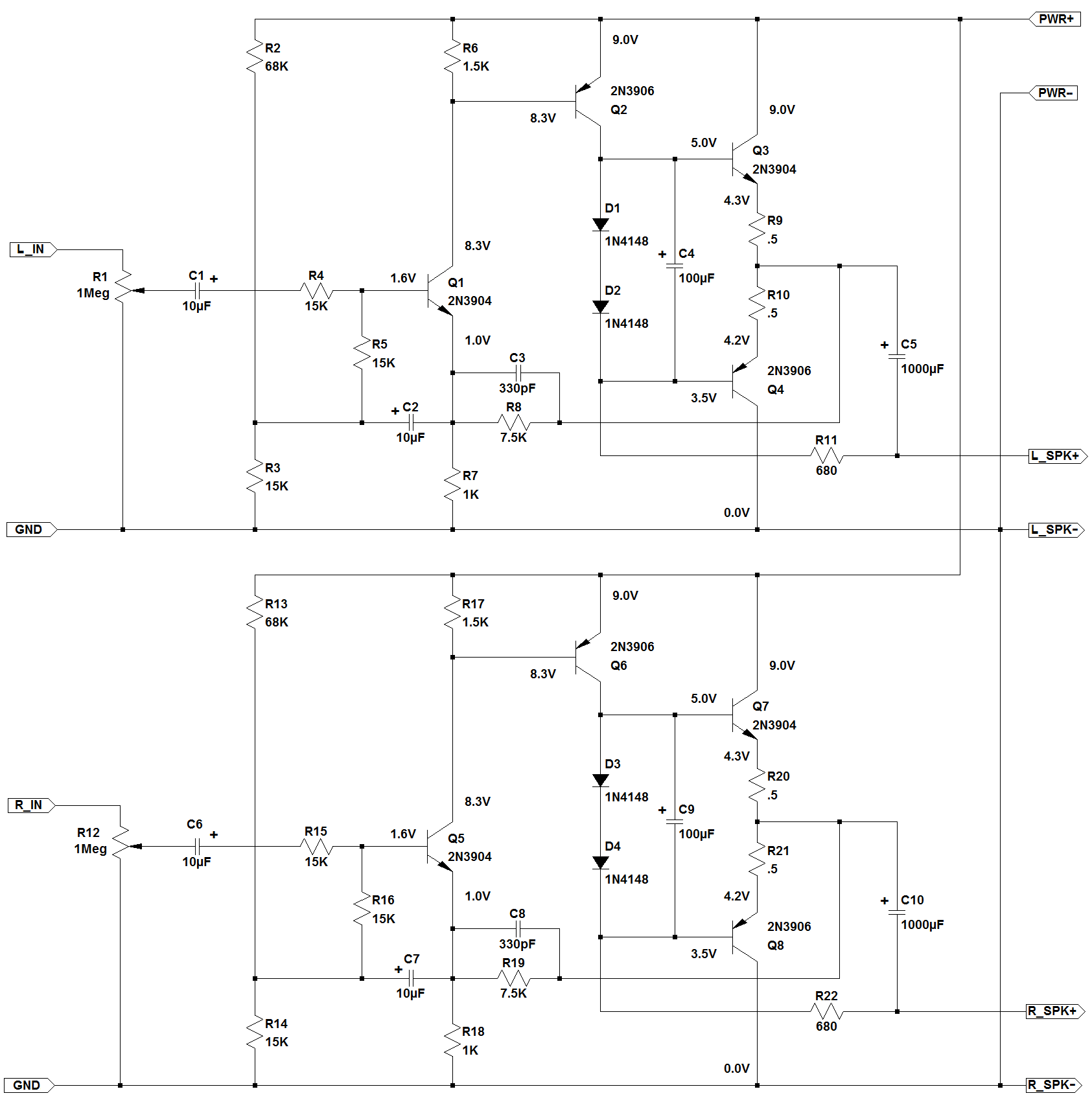
Stereo Amplifier Schematic
The right and left channel amplifiers are identical so I will only describe the left channel in this section.
There are three stages in the amplifier: A differential amplifier (Q1), a Common Emitter driver (Q2), and a Push-Pull Output (Q3 and Q4).
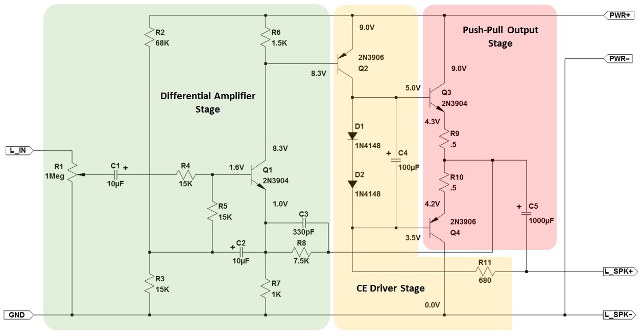
Amplifier Stages
Differential Amplifier Stage
The Differential Amplifier stage provides three essential functions for the remaining stages:
1. A bootstrap bias circuit consisting of C2 and R2-R5 that increases amplifier input resistance to approximately 2M Ohms.
2. A DC feedback loop composed of R7 and R8 for controlling the overall amplifier gain, reducing distortion, and keeping the push-pull output voltage centered at 1/2 power supply voltage.
3. A first order low pass filter composed of C3 in combination with R7/R8 that limits high frequency response to 65Khz.
Resistors R2 and R3 form a voltage divider bias circuit for Q1 that sets the collector voltage around 8.2V and collector current at 500uA. Voltage gain for the Differential Amplifier is -21db (loss) and the signal phase shift is 180 degrees so another amplifier stage is needed to correct this before sending the signal to the output stage.
Don't be concerned about the first stage looking a little unusual. It's not the canonical differential amplifier covered in circuits class that uses two transistors. The 8 transistor stereo amplifier project needed to run on only 4 transistors per channel and so the design did away with one of the differential amplifier transistors and made use of the emitter circuit as an input. It has some limitations, but it does work.
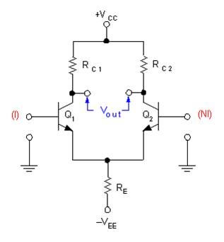
Standard Differential Amplifier
For those that would like to experiment on their own with this portion of the circuit to see how it really works, I have provided a quick design similar to the one used in the amplifier project and included the schematic below. It's only a few components and can be wired up on a solderless breadboard.
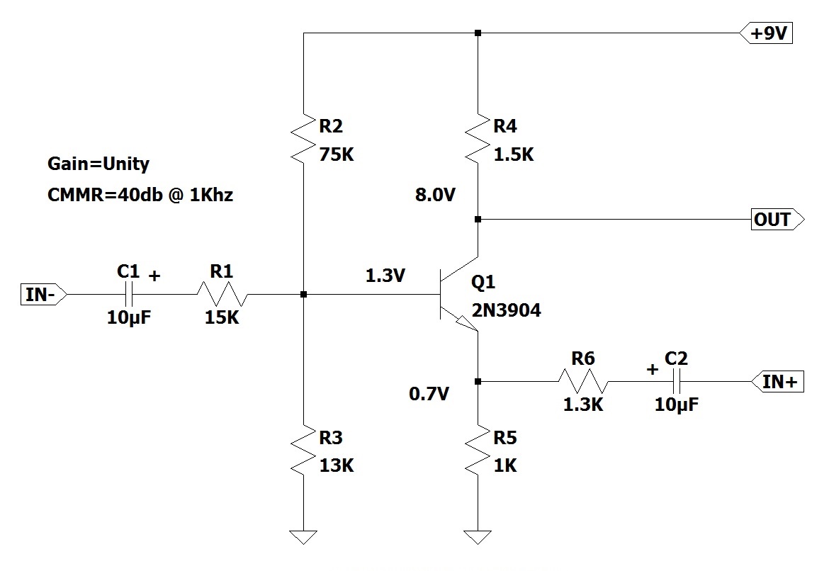 Single Transistor Differential Amplifier
Attach a signal generator to the IN+ terminal, ground the IN- terminal, and then attach Channel 1 of a dual trace oscilloscope to the OUT terminal and Channel 2 to the IN+ terminal. Set the signal generator to 1Khz with a 1Vpp output. The oscilloscope trace should look like the first trace below. Notice that the Differential Amp input and output are in-phase and the amplifier gain (Vpp OUT / Vpp IN) is approximately equal to one.
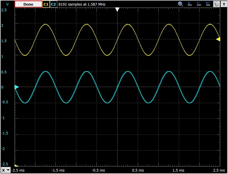
Non-Inverting Input (Yellow) and Differential Amplifier Output (Blue) - In Phase
Remove the signal generator and oscilloscope. Attach the signal generator to the IN- terminal, ground the IN+ terminal, and then attach Channel 1 of a dual trace oscilloscope to the OUT terminal and Channel 2 to the IN- terminal. The oscilloscope trace should look like the second trace below. Notice that the Differential Amp input and output are 180 degrees out of phase and the amplifier gain (Vpp OUT / Vpp IN) is approximately equal to one.
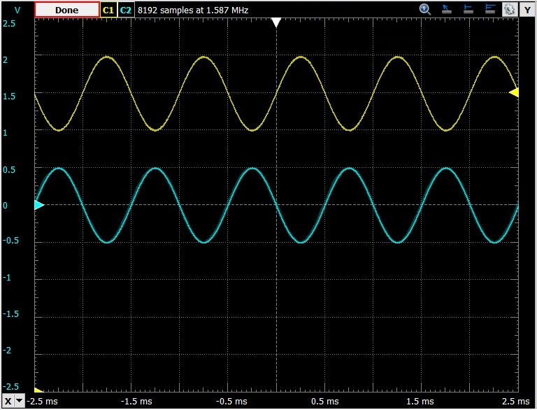
Inverting Input (Yellow) and Differential Amplifier Output (Blue) - 180 Degree Phase Shift
This is the behavior expected from a differential amplifier with a gain of 1. You would see similar behavior from an Operational Amplifier IC or a canonical 2 transistor Differential Amplifier.
One critical measure of differential amplifier performance is Common Mode Rejection Ratio (CMMR). If you apply a signal of the exact same amplitude and phase to the IN+ and IN- terminals of a differential amplifier, the output should be zero. If it isn't, then the amplifier has introduced some error in the output. Practical diffamps aren't perfect so CMMR is often used as a measure of quality. Commercial Operational Amplifier ICs typically achieve CMMRs between 70db and 100db depending on signal frequency. The simple one-transistor differential amplifier won't be that good, but after all it's only one transistor.
To determine the CMMR for the diffamp circuit shown above, replace R6 with a 2K Ohm trimmer resistor (Pin 1 to Q1 Emitter, Pin 2 to C2+). Attach both the IN+ and IN- terminals to the signal generator. Turn off Channel 2 of the oscilloscope and adjust Channel 1 until a signal is displayed. Adjust the trimmer resistor until the the diffamp output voltage is as low as it will go. The output should be around 10mv peak-to-peak as shown in the trace below.
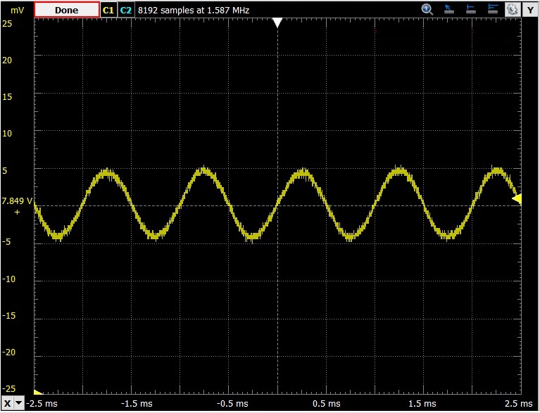
Non-Inverting and Inverting Inputs Tied Together Showing Common Mode Output
The following calculation provides the CMMR value of this differential amplifier:
Differential Mode Gain = OUT / (IN+ - IN-) = 1Vpp / (1Vpp - 0Vpp) = 1
Common Mode Gain = OUT / IN = 0.01Vpp / 1Vpp = 0.01
CMMR = Differential Mode Gain / Common Mode Gain = 1 / 0.01 = 100
CMMRdb = 20 * log (CMMR) = 40db
So this differential amplifier circuit is very simple, uses only one transistor, and can be scaled for various differential mode gains.
But...
It's CMMR isn't as good as a canonical diffamp or an OpAmp, and the input impedance on the non-inverting input is pretty low (around 1500 Ohms).
But if you take these into consideration it is easy to design a small amplifier that performs really well with just a few transistors.
Common Emitter Driver Stage
This is the voltage gain stage of the amplifier. Q2 amplifies the output of Q1 and provides +45db of voltage gain which is used to drive the push-pull output stage. To maximize gain and output voltage swing, Q2 doesn't use emitter degeneration so it's collector output will be fairly non-linear and temperature dependent. This is corrected with the DC feedback loop R7 and R8.
Collector current for Q2 is set at 5mA and flows through the speaker, R11, D1, and D2. This small current through the speaker isn't enough to generate measurable power or audible noise, but it provides a small feedback signal in the collector circuit of Q2 that corrects crossover distortion in Q3/Q4.
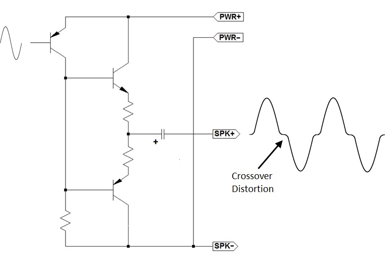
Crossover Distortion without Push-Pull Bias
The original amplifier circuit used a resistor to set the quiescent current for Q3/Q4. The voltage drop on that resistor was proportional to the collector current in Q2 and just slightly turned on Q3/Q4 so the amplifier would operate in a Class A mode for small signals. Unfortunately as the temperature changed in Q3/Q4, their base current would increase raising the voltage drop on the resistor. As the voltage drop on the resistor increased, the Q3/Q4 quiescent current would increase raising their temperature. This cycle would repeat until the temperatures of Q3/Q4 became so high they self destruct.
To avoid this, I've replaced the original resistor bias with D1 and D2. The combination of these two diodes provide a 1.4V bias for Q3/Q4 that is almost independent of the base current from Q3/Q4. Not exactly independent but much closer than a resistor. D1 and D2 also have a negative temperature coefficient with respect to junction voltage. So as the ambient temperature increases which tends to increase current in Q3/Q4, the junction voltage of D1/D2 decreases which reduces current in Q3/Q4. Ideally D1 and D2 should be physically close to Q3/Q4 (mounted on the heat sink if possible) but the diode stabilization circuit used here has worked extremely well in my temperature and output power tests. Capacitor C4 prevents ringing during Q3/Q4 crossover.
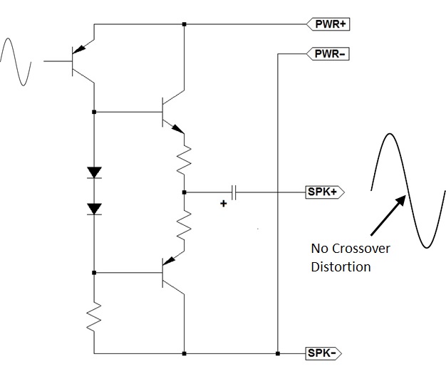
No Crossover Distortion with Push-Pull Diode Bias
Push-Pull Output Stage
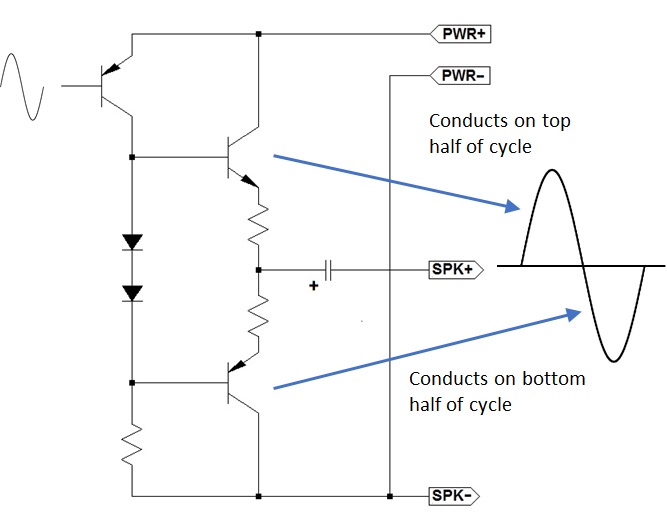
The Push-Pull output stage provides the current gain needed in combination with the voltage gain of the CE Driver to produce the output power that drives the speaker. Q3 and Q4 work independently for large signals (Class B operation) but in tandem for small signals (Class A operation). For large signals, Q3 will conduct for one half of a cycle while Q4 will conduct for the other half. For small signals, Q3 and Q4 will contribute to both halves of the cycle.
The DC output voltage on Q3/Q4 is 1/2 the power supply voltage in order to provide for the maximum AC voltage swing without clipping distortion. For a 9V battery, the Push-Pull DC output voltage is 4.5V. We don't want this DC voltage to appear on the speaker as that will waste a lot of power heating up the speaker coil and generating no sound in the process. We only want the AC voltage from the CE Driver stage to appear at the speaker. C5 decouples the DC output voltage on the Push-Pull stage from the speaker and allows only the AC voltage to appear. The trade-off with coupling capacitor C5 is that at low frequencies, the impedance of C5 will reduce the output voltage to the speaker which limits the lowest frequency from the music source that can be amplified which in this case is around 27 Hz.
The voltage gain of the Push-Pull output stage is -6db (loss) but the current gain for the Push-Pull stage is +35db which allows a tiny current in Q2 to produce a large current in Q3/Q4. The overall voltage gain of the amplifier is the sum of all the stage gains:
Diff Amp Gain + CE Driver Gain + Push-Pull Gain = (-21db) + 45db + (-6db) = +18db
Operating Parameters
After building the amplifier, the following operating parameters were measured with a power supply of 9V:
DC Quiescent Supply Current = 11mA per channel (22mA total)
Max Voltage Swing = 6Vpp
Power Supply Rejection = -20dB
Voltage Gain = +18db
Output Power at 1% THD = 0.525 W per channel
Input Impedance = 700 K Ohms
Frequency Response +/- 1db = 35 Hz to 20 KHz
Low Cutoff = 27 Hz
High Frequency Cutoff = 65 Khz
How to build the 8 Transistor Stereo Amplifier
The 8 Transistor Stereo Amplifier project described here is based on the Radio Shack pbox kit of the same name, but it has been updated with silicon transistors and passive components that can be easily obtained from electronics suppliers like Mouser and Digikey. I've built the redesigned amplifier kit described here and believe it works better than the original kit did back in 1969. To make it easy to replicate my work, I've provided illustrations and step-by-step assembly documentation based on the publication style used for the original product. But every page was created with original content specifically for the redesigned amplifier.
Download the Assembly Manual >>> HERE <<<.
I built the kit in two evenings, taking my time, and double-checking my progress while following the manual. If you are familiar with breadboard construction techniques, you can probably complete the project in a single evening.
Important Note:
Be sure to read through the "Tweaks and Hacks" section before you order parts and start building. You might want to include some of the suggested modifications during construction or dream up your own before you start.
Obtaining parts for the Stereo Amplifier project
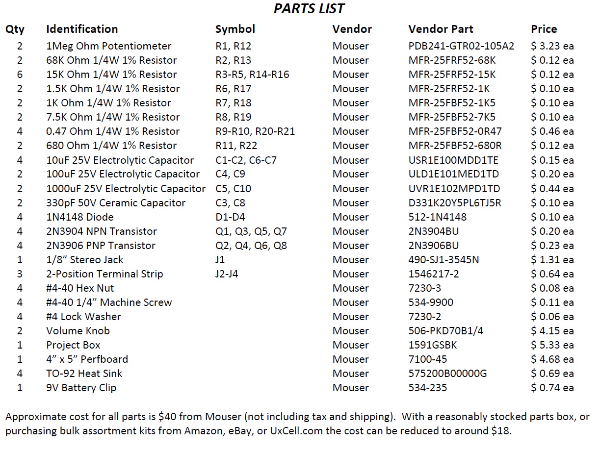
Review the parts list and obtain the components indicated. All components are available from Mouser or Digikey, or can be obtained from other suppliers that may be more convenient to your geography. Total cost for all new parts in small quantities is around $40 not including tax and shipping. To put that cost in perspective, the 8 Transistor Stereo Amplifier kit was introduced in 1969 at a retail price of $8.95. The economic value of $9 in 1969 is equivalent to around $61 today. If you deduct the cost of the volume knobs I've specified (knobs weren't included in the original kit) the amplifier project can be built for about half the adjusted cost of the project kit offered by Radio Shack in 1969. But keep in mind that Radio Shack needed to make a profit from the sale and support of their kit which explains the catalog price.
Below are a few notes regarding the parts used for the 8 Transistor Stereo Amplifier project:

NOTE: As of 2026, Joe Knows Electronics is no longer in business. I have left the content in place for historical purposes. There are many sellers on Amazon offering resistor assortments at great prices.
1. The resistors for the project can be purchased from Mouser, Digikey, Newark or other electronics component retailer. But I highly recommend the excellent Joe Knows Electronics resistor kit. It includes most (but not all) of the resistors you need for this project and over 860 different values that can be used for other projects, all labeled in individual plastic packages for $20. For this project I used all 1/4W resistors to save space. You can also find good deals on resistor kits from Amazon by searching for "resistor kit" and looking for a 1% tolerance kit that includes the most values and parts count for the best price. Some really good resistor kits can be found for less than $20. I've done that several times and have always been happy with the parts I received regardless of supplier.
2. The capacitors for the project can be purchased from Mouser, Digikey, Newark or other electronics component retailer. I used capacitors from the Joe Knows capacitor kit and an electrolytic assortment I found on Amazon for $10.
3. The transistors for the project are common 2N3904/2N3906 transistors that can be found just about anywhere by searching on the transistor number. All of the semiconductors I used came from the Joe Knows semiconductor kit. This is a great component assortment that comes with three booklets explaining how the components work and provides some example circuits to help illustrate how to hook them up in a circuit.
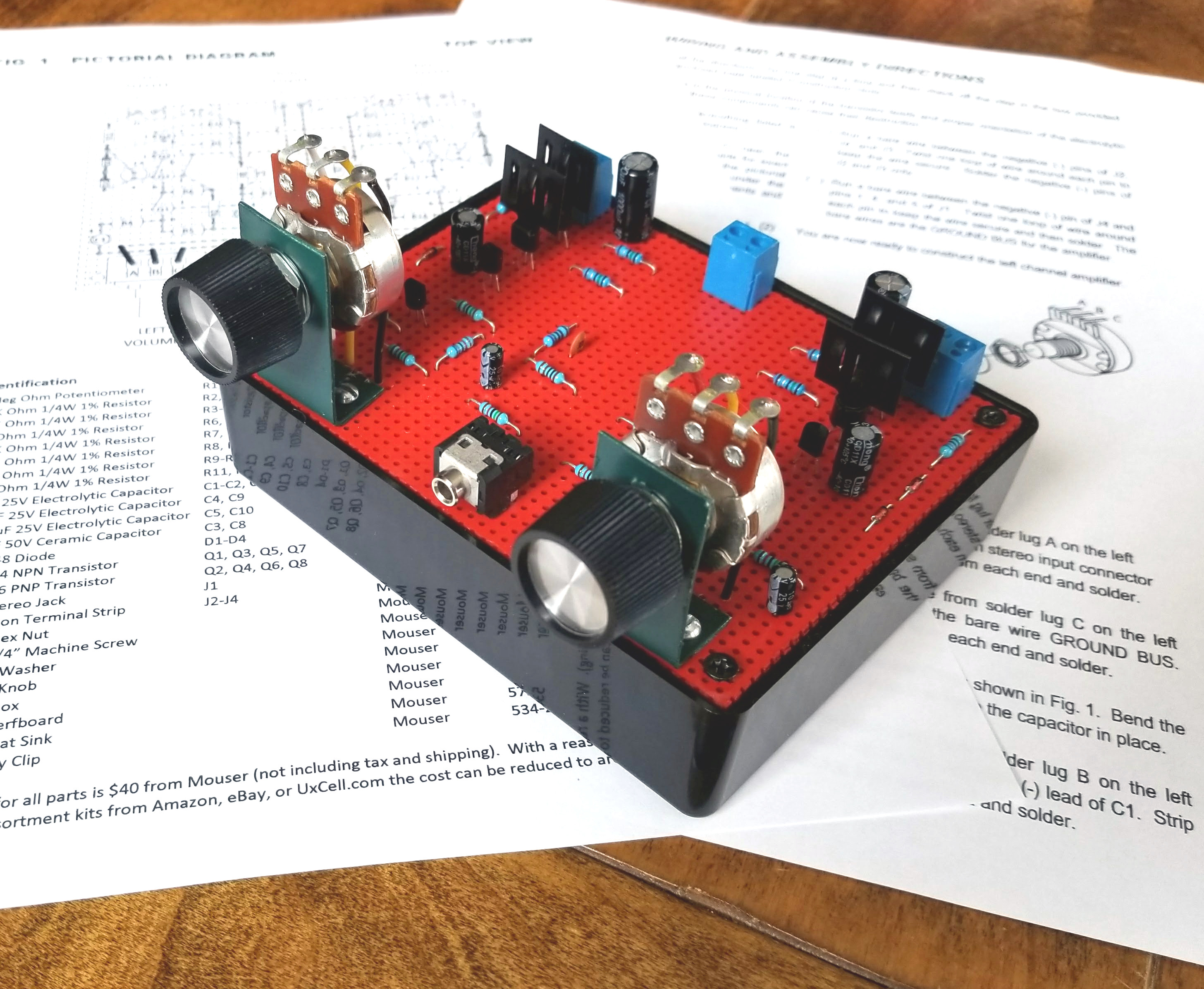
4. The case for the Stereo Amplifier project I built is a Hammond 1591GSBK ABS Project Box from Mouser. I used a piece of vector breadboard cut to fit on the top and spray painted with high temperature automotive flat red and finished with clear coat. I like the look of red on black, and the red color of the breadboard matched the red color of the original pbox kit. It's completely up to you how you want to house and color the kit you build.
5. The original pbox kit used tin-plated spring clips for attaching the battery, speakers, and input connections to the perf-board enclosure. These clips were a pain to solder to when new and they tarnished like crazy after they were installed resulting in intermittent connections. Fortunately for everyone they are no longer available. For this project I found that two position terminal strips and a 1/8" (3.5mm) stereo jack were a better solution.
Please Note: I have no business relationship with any of the above vendors. Nothing of financial value was exchanged for my recommendation. None of the above vendors provided compensation of any kind during the creation of this project. I will not be compensated in any way if you choose to build this project or purchase components from any vendor I recommend. I simply had a good experience with the vendors I recommend and believe you will too.
A bit of history associated with this project
The original circuit design for the Stereo Amplifier from Radio Shack used 8 germanium transistors arranged in three stages: Differential Amplifier, CE Driver, and Push-Pull Output. These stages were common in high-end commercial amplifier design so the 8 Transistor Stereo Amplifier project should have earned a lot of fans back then. However, after only 3 years the kit was withdrawn which suggests that after the initial catalog marketing interval the product was only around for a year. When the kit was produced in 1969, Silicon junction transistors had replaced Germanium in new commercial amplifier designs. However, GE and ETCO continued selling Germanium transistors to hobbyists until about 1979 through Radio Shack, Lafayette, Poly Paks, and others. So, why did the kit not have a successful run?
Well, there are some good reasons:
Germanium was a relatively easy element to work with during the early days of the transistor but it's weaknesses made Silicon a more attractive element after manufacturing challenges were overcome. Germanium has a lower energy gap between the valence and conduction band which results in higher leakage current proportional to temperature. Germanium has lower thermal conductivity than silicon which makes it harder for the transistor get rid of internally generated heat. As internal temperature rises, more leakage current occurs which generates more heat... and so on. These two properties combined can result in thermal runaway ending in device self destruction. The original amplifier design did not provide a method for preventing thermal runaway in a push-pull configuration which made the amplifier unreliable.
By 1959 no manufacturer had discovered a way to build an oxide on Germanium. This allowed Silicon oxide planar transistors to achieve manufacturing dominance in terms of yield, cost, and reliability. As the cost of Silicon transistors fell, Germanium could not keep up and eventually the transistors used in the kit became too expensive. To minimize the potential for thermal runaway, Radio Shack sold matched pair semiconductors that were sorted by hand which further increased the cost of the transistors.
At $9.00 ($61 in 2017) the 8 Transistor Stereo Amplifier was the most expensive kit in the Pbox line and contained 56 parts. By comparison the 3 Transistor Short Wave Radio kit at $8 had only 39 parts and the FM Wireless Microphone kit at $7 had only 23. I suspect there were very few young customers able to afford a product this complex, and there were more factory rework and refund returns than anticipated.
So...
To overcome the limitations of the original kit, I've included a few modifications to improve performance and reliability including:
1. Redesign the amplifier to use readily available Silicon transistors.
2. Improved bias control for push-pull stage.
3. Increase output coupling capacitance to improve low frequency response.
4. Add compensation capacitor to increase high frequency roll-off above audio frequencies.
5. Replace tin-plated spring terminals with terminal strips and stereo jack to improve connection reliability.
6. Re-scale amplifier gain for maximum power at modern line level voltages.
I haven't attempted to simplify the project. My redesign requires 69 parts and the assembly document is 9 pages long. So I do not recommend this project for a novice. But if you like working with discrete analog components on perfboard and you have good soldering skills, this project is just the right challenge.
I think this kit redesign is far and away the most fun I've had working on these Pbox redesigns. The 8 Transistor Stereo Amplifier project I built can easily fill a room with great sound when attached to a set of good speakers. It's impressive what can be achieved with a few transistors and a standard 9V battery (even if that battery won't last long at full power).
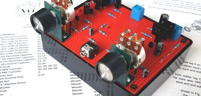
Review the circuit board layout
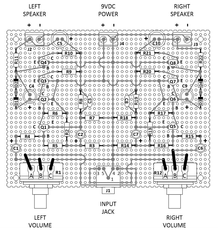
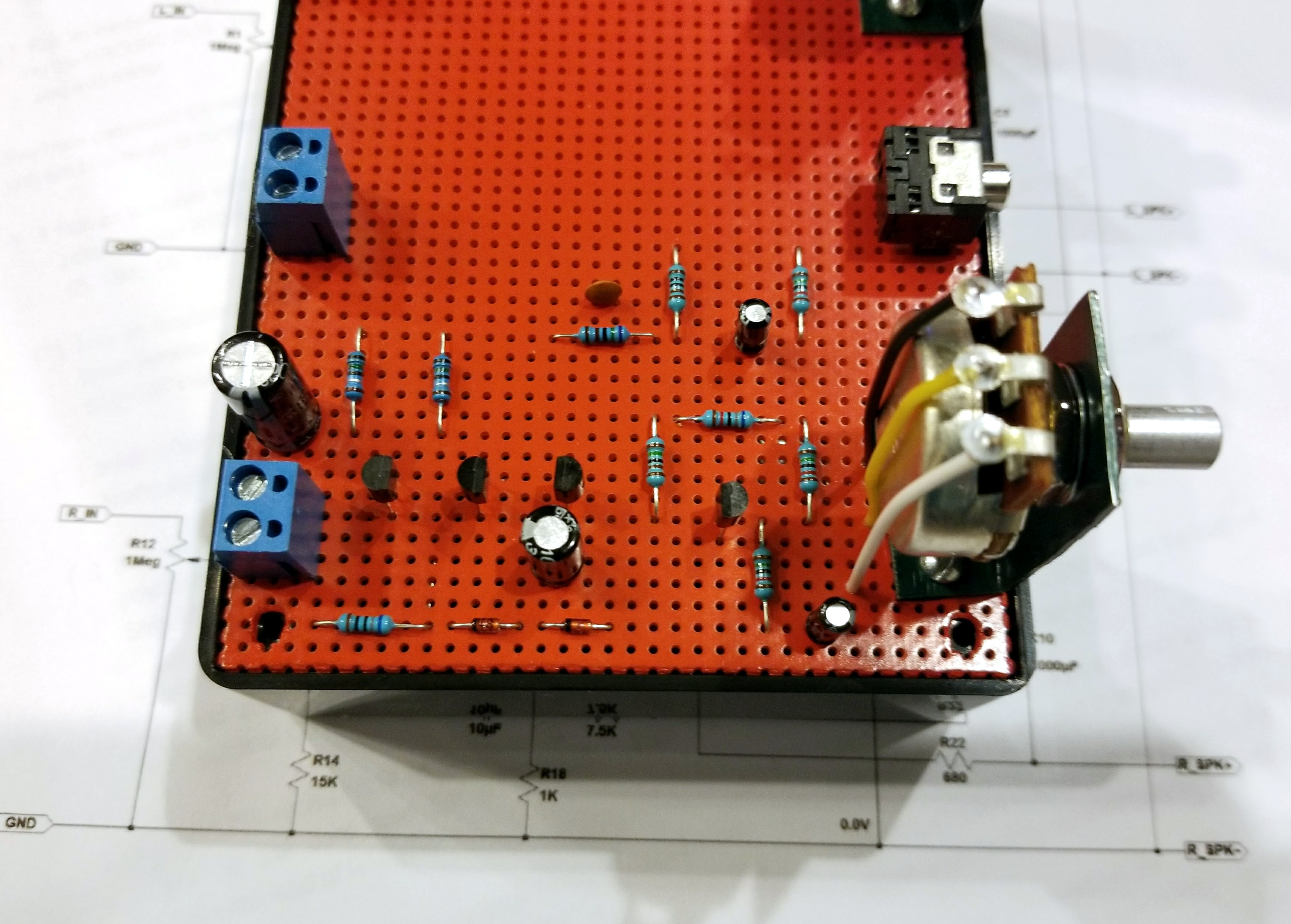
Circuit Board Layout (Top)
The Assembly Manual provides a step-by-step checklist for installing and soldering each component to the pefboard. As you can see from the opposite side illustration, I've used point-to-point wiring with 24 AWG solid hookup wire. Most of the connections can be made with just the component leads. But power, ground, and signal bus leads are best done with lengths of hookup wire.
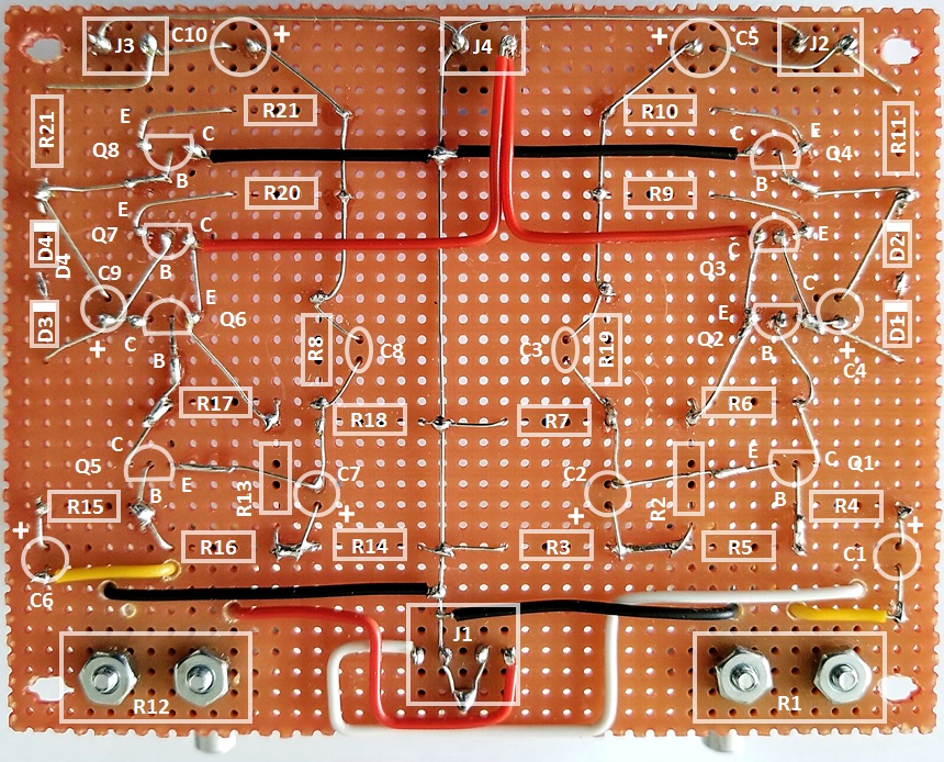
Circuit Board Layout (Bottom)
When it comes to wiring, try to be as neat as I've indicated in the assembly manual. You don't have to be the world's best soldering artist but there's no good reason to do the work half-way. Go all out and make your project look as good as you can.
Preparing the perfboard before mounting components
The perfboard specified in the parts list is too large to fit onto the Hammond case so some trimming is required as indicated in the images below. Follow the steps below to prepare the perfboard before installing components:
Warning: When I write, "sharp edge" I mean Xacto knife or similar. Those products are extremely sharp (think surgical scalpel) and can do a lot of damage if you aren't extremely careful. Use extreme care when operating any cutting tool.
1. Using a sharp edge, carefully score the perfboard along the TOP ROW and BOTTOM ROW row of holes all the way to the end of the board. Run the sharp edge over the score line several times until it penetrates 1/4 to 1/2 way through the perfboard.
2. Using a sharp edge, carefully score the perfboard along the RIGHT COLUMN and LEFT COLUMN of holes all the way to the end of the board. Run the sharp edge over the score line several times until it penetrates 1/4 to 1/2 way through the perfboard.
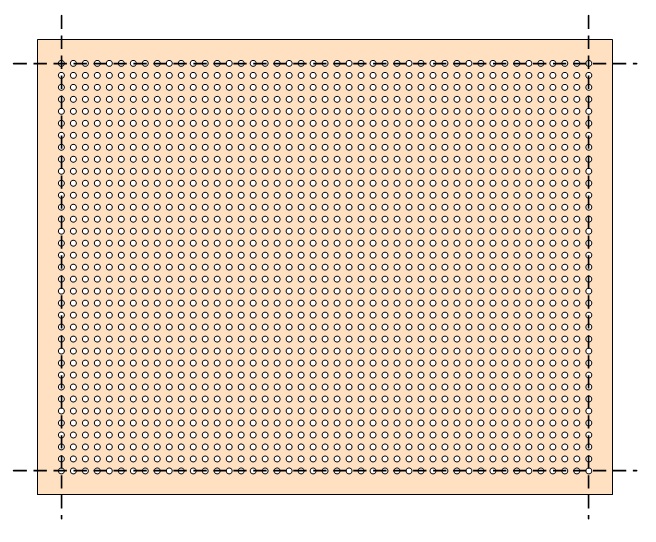
Score edges of perfboard along dashed lines
3. Using a small pair of pliers, carefully bend the TOP ROW section back away from the score line. Work with one end of the TOP ROW, moving to the center, and then the other end. The TOP ROW section will eventually break away from the perfboard.
4. Using a small pair of pliers, carefully bend the BOTTOM ROW section back away from the score line. Work with one end of the BOTTOM ROW, moving to the center, and then the other end. The BOTTOM ROW section will eventually break away from the perfboard.
5. Using a small pair of pliers, carefully bend the RIGHT COLUMN section back away from the score line. Work with one end of the RIGHT COLUMN, moving to the center, and then the other end. The RIGHT COLUMN section will eventually break away from the perfboard.
6. Using a small pair of pliers, carefully bend the LEFT COLUMN section back away from the score line. Work with one end of the LEFT COLUMN, moving to the center, and then the other end. The COLUMN section will eventually break away from the perfboard.
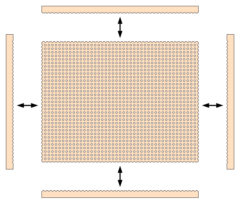
Carefully break apart perfboard edges along score lines
7. Using an Exacto knife, match the trimmed perfboard with the Hammond case and enlarge holes at the corner to match with the corner mounting holes in the case. Work slowly and carefully with minimal pressure to avoid breaking the corner piece.
8. Place the potentiometer mounting brackets onto the perfboard and enlarge holes in the perfboard to match the holes in the brackets. Work slowly and carefully with minimal pressure to avoid cracking the perfboard.
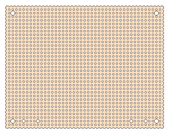
Cut holes for case and bracket screws
9. Spray paint the perfboard with the color of your choice or leave it natural. It's your choice.
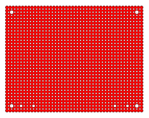
Paint with desired color
I typically use flat red followed up with 2 to 3 coats of gloss clear.
Fabricate and mount the volume control brackets
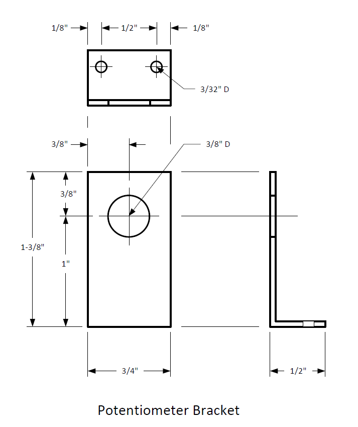
The volume control brackets I made were from an old license plate that I cut with tin snips. But you can use any thin metal you have available. I've used PCI slot covers from an old desktop computer to good effect as well. I spray painted the brackets with a dark grey automotive paint but you can use any color that looks cool to you. There is no try. Do, or do not.
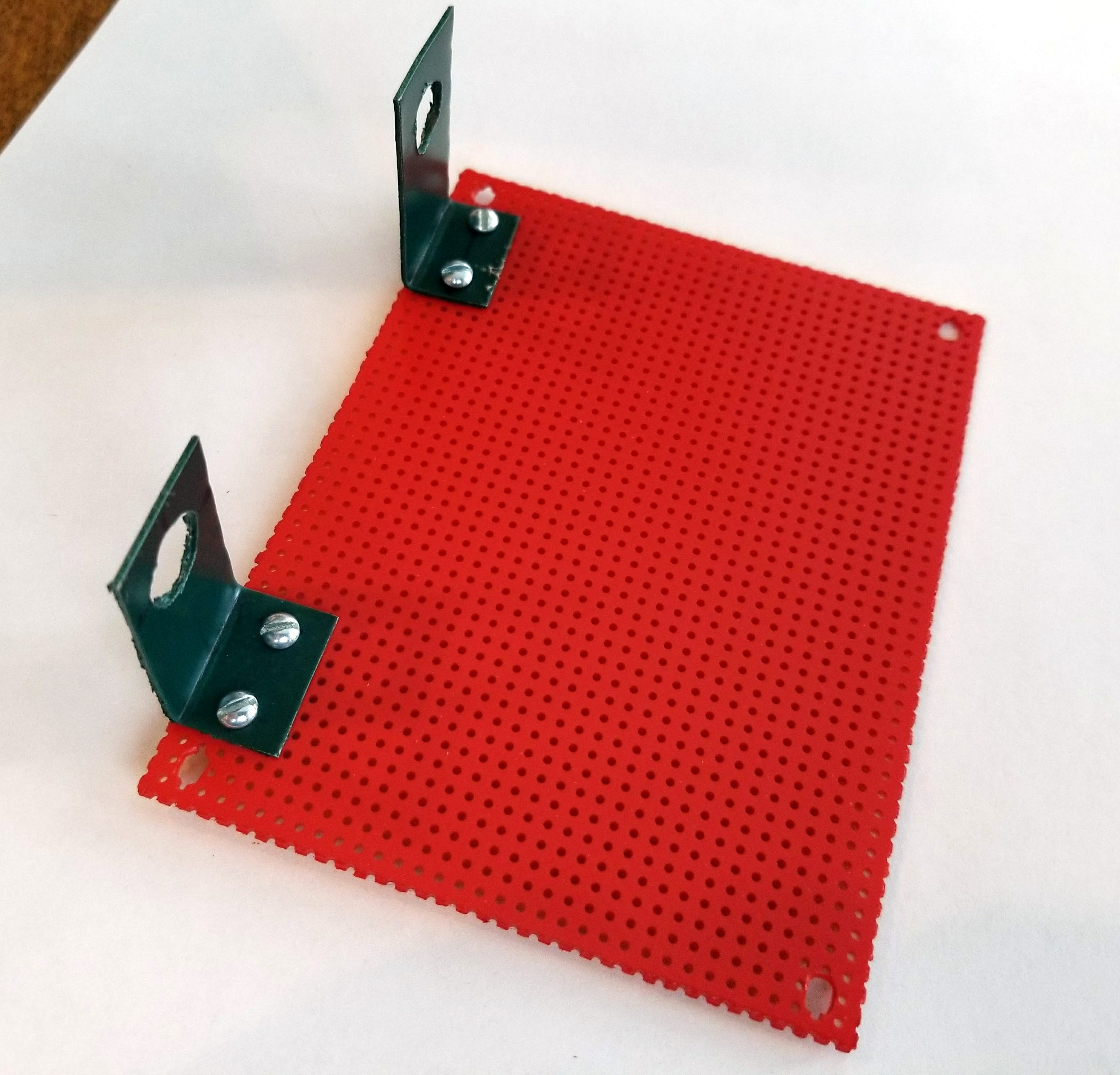
Follow the first few steps in the assembly manual to install the volume control mounting brackets. When completed, the project should look something like the images below.
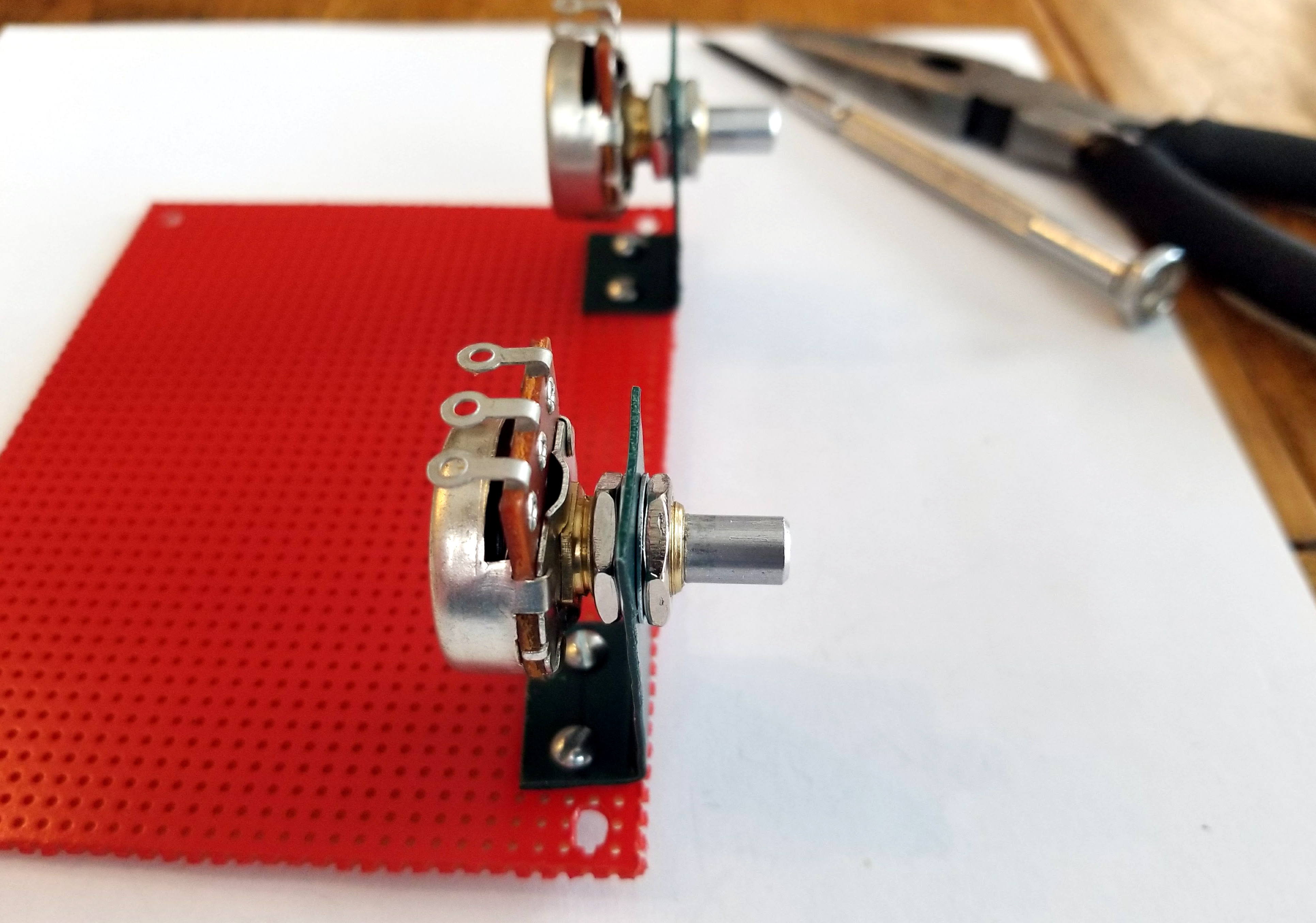
Mount the Volume Controls
The potentiometers specified in the parts list come with hex nuts and flat washers. The assembly manual shows the order in which to install this hardware. So that the potentiometer shaft does not extend out too far from the bracket, I installed the inside hex nut and flat washer so that the outside hex nut and washer would sit just inside the first couple of threads on the shaft.
Important Note: If you use a different vendor for the potentiometers than I've specified, make sure they ship with mounting hardware or you will need to purchase your own.

The potentiometers and their mounting hardware
Position of mounting hardware on the bracket
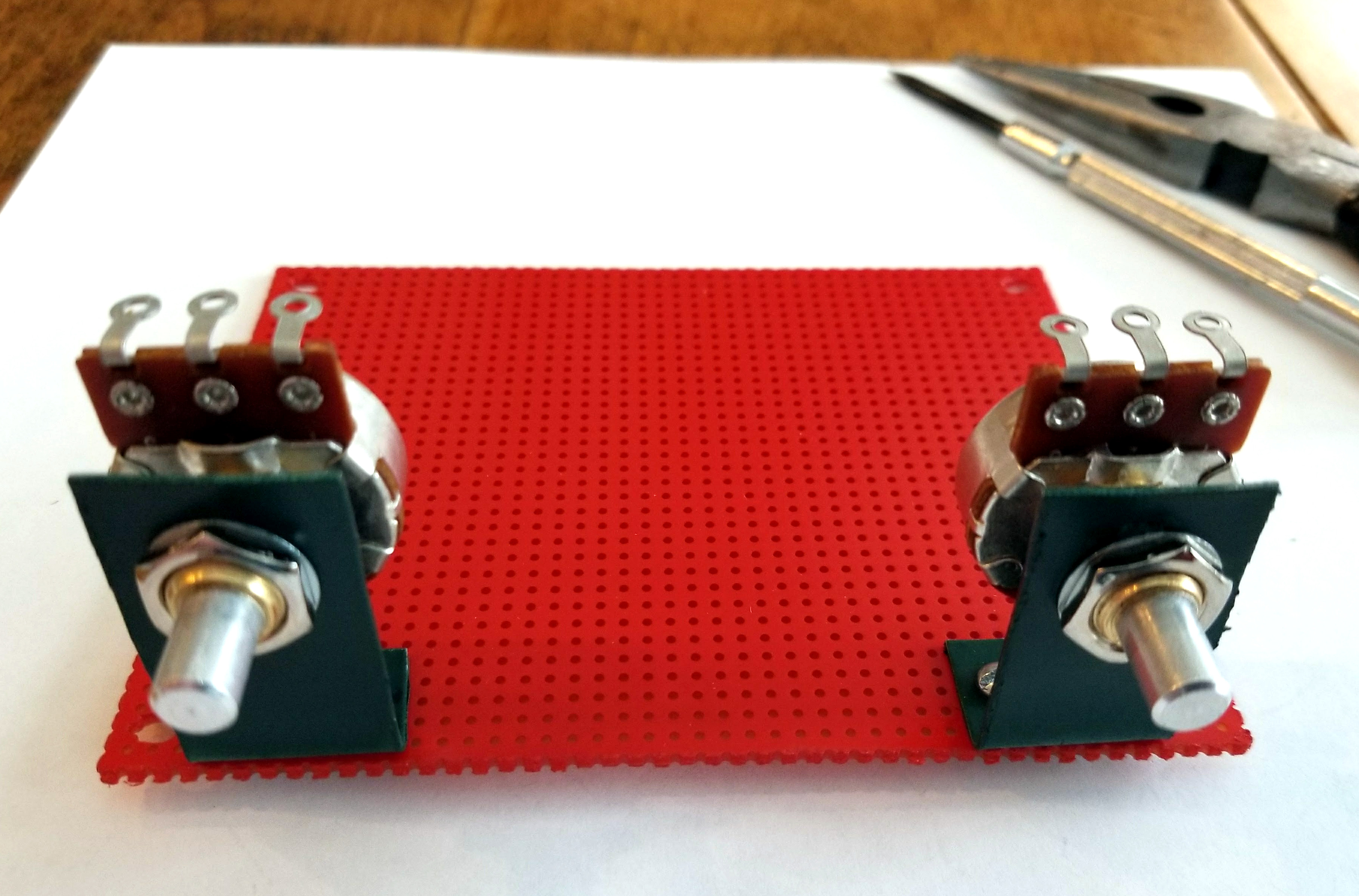
Potentiometers and hardware installed
Install input, speaker, and power connectors
The 1/8" (3.5mm) stereo jack specified in the parts list comes with pins pre-formed for automatic insertion into a PCB board. I straightened the pins out with pliers, lined up the pins on the perfboard, and firmly pressed down on the connector to seat it flush. You may need to slightly enlarge the perfboard holes if the connector will not seat with moderate force. Do not apply excessive pressure.
The three 2-position terminal strips will sit flush on the perfboard with very little force. Bend the pins slightly outward to keep them in place.
The assembly manual covers these steps, but I wanted you to be able to see what the board should look like when all connectors are installed.
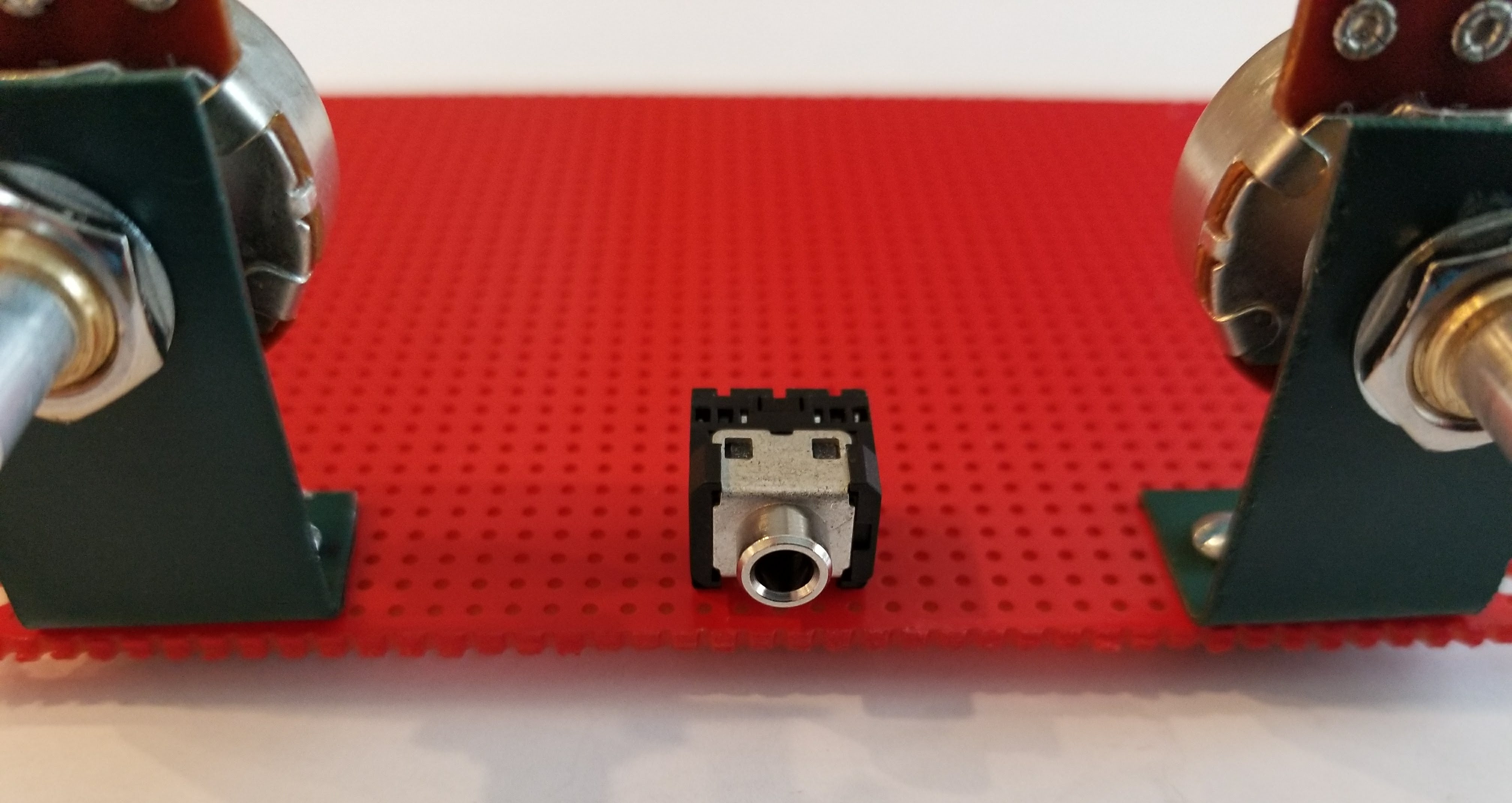
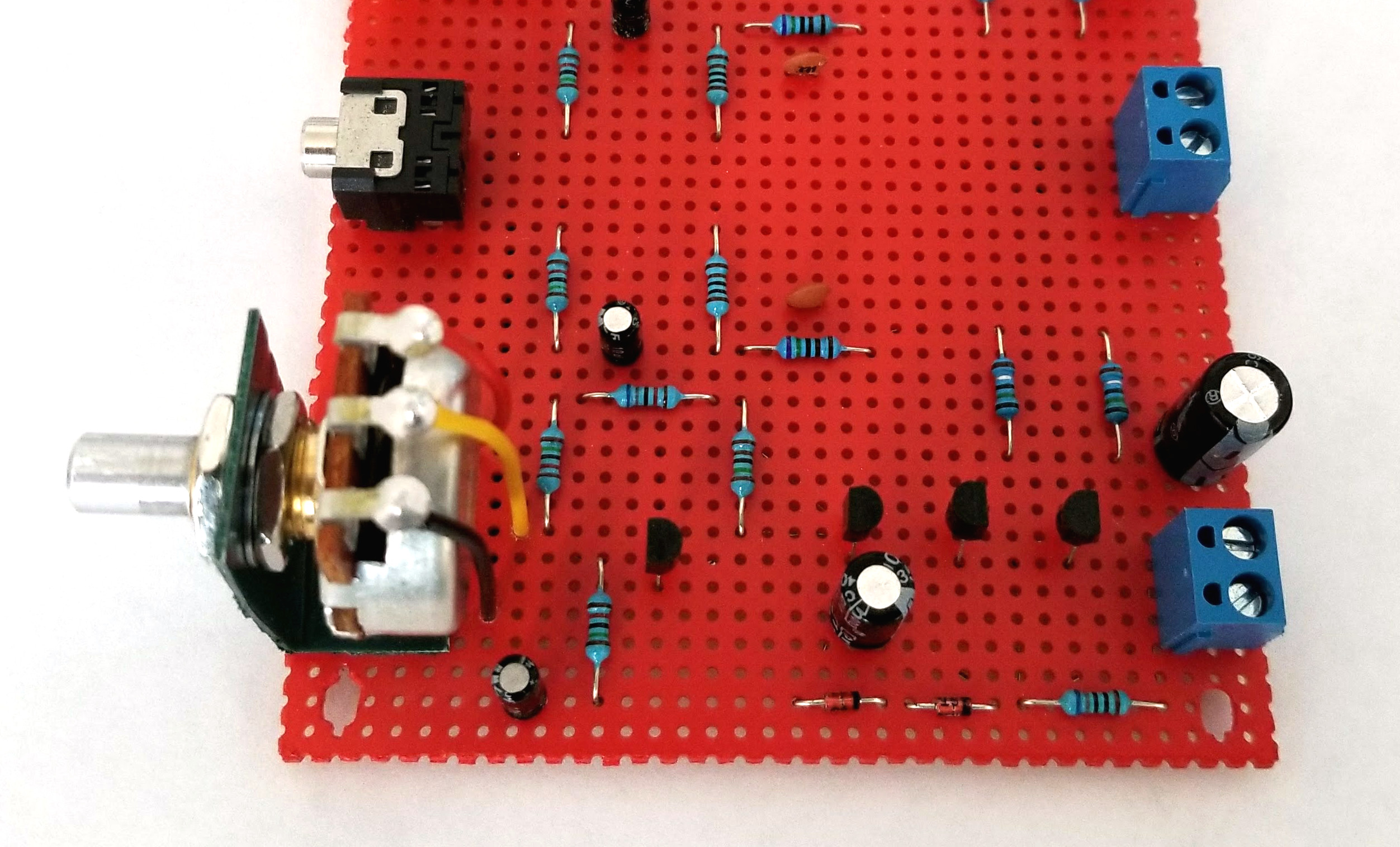
Stereo Jack Installed
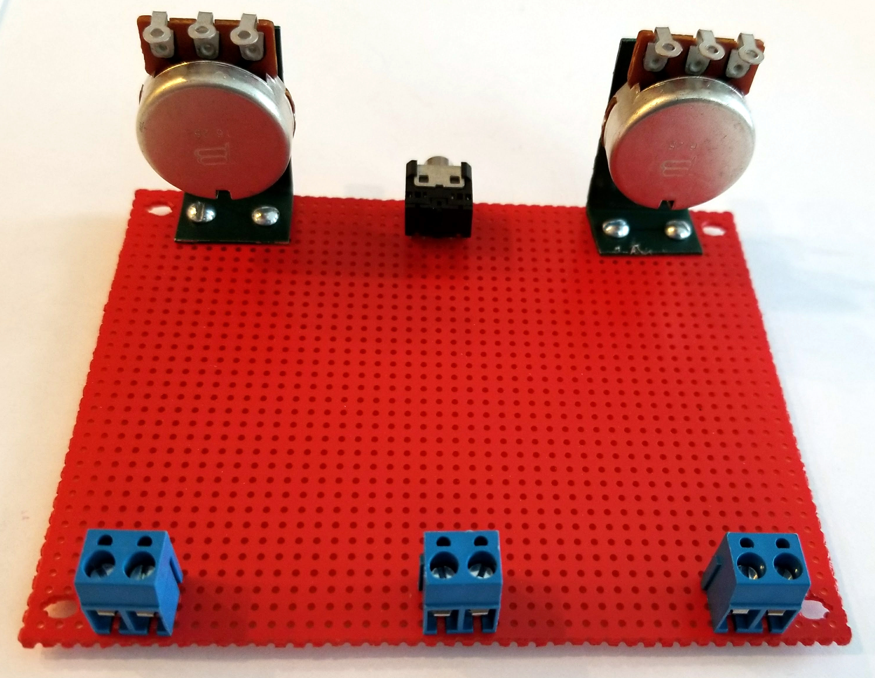
Speaker and Power Connectors Installed
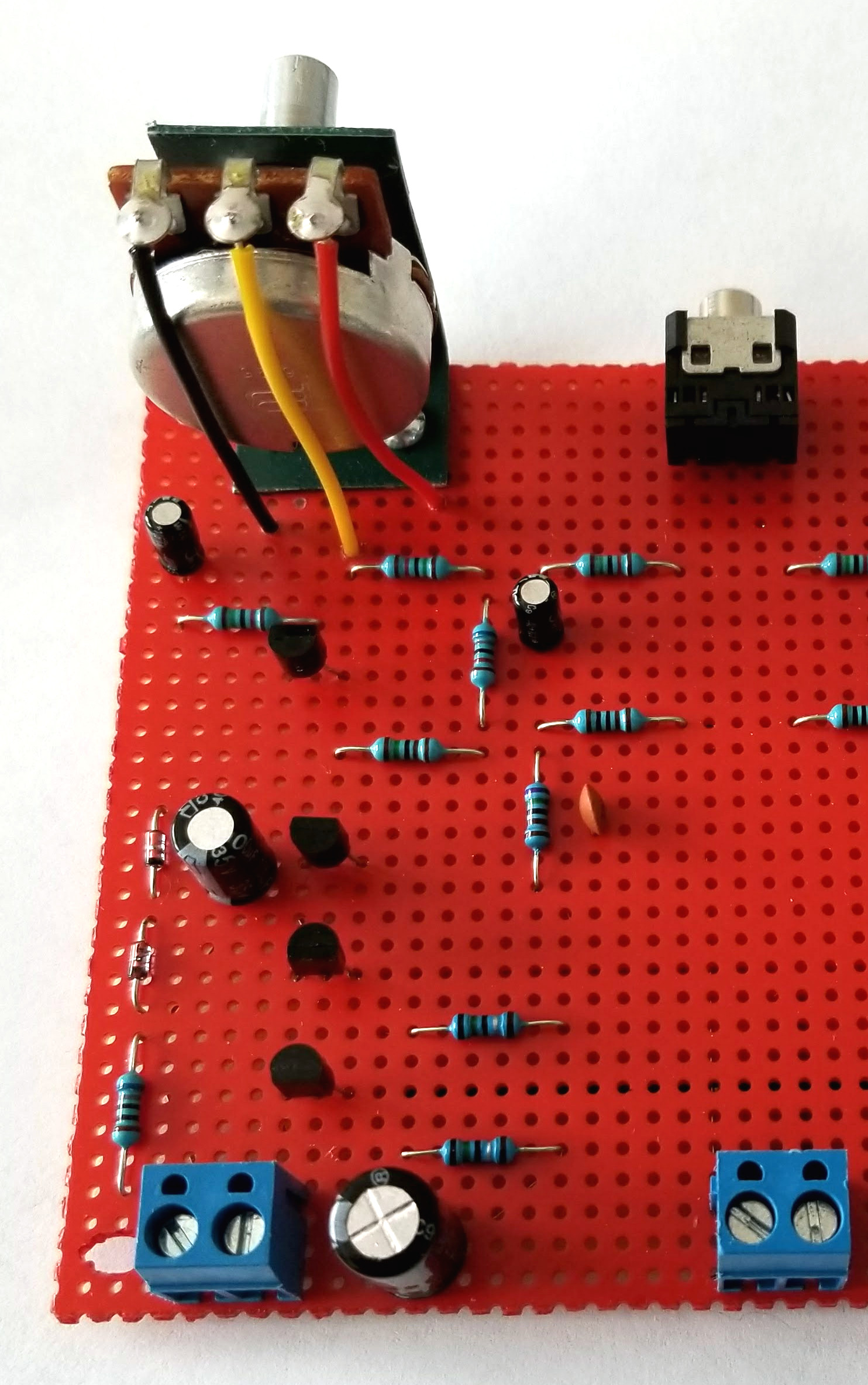
Assembly Photos: Completed Left Channel
When completed, the left channel amplifier should look something like the images below. I used colored hookup wire for the potentiometer connections so it would be easier to identify each potentiometer lug (A, B, or C).
Assembly Photos: Completed Right Channel
When completed, the right channel amplifier should look something like the images below. I used colored hookup wire for the potentiometer connections so it would be easier to identify each potentiometer lug (A, B, or C).
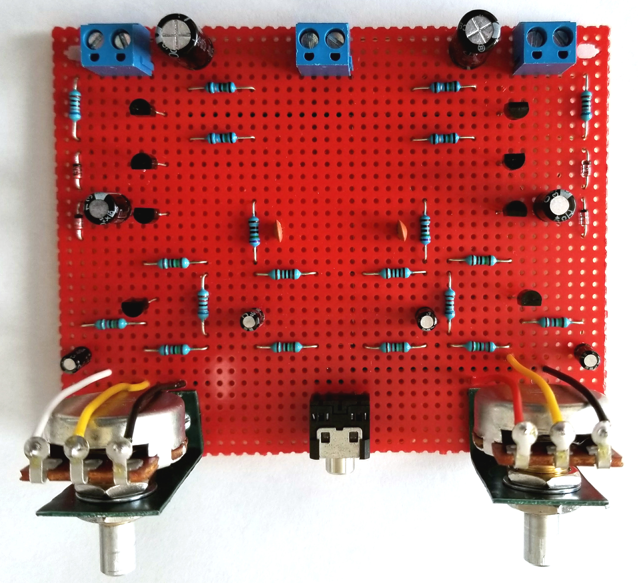
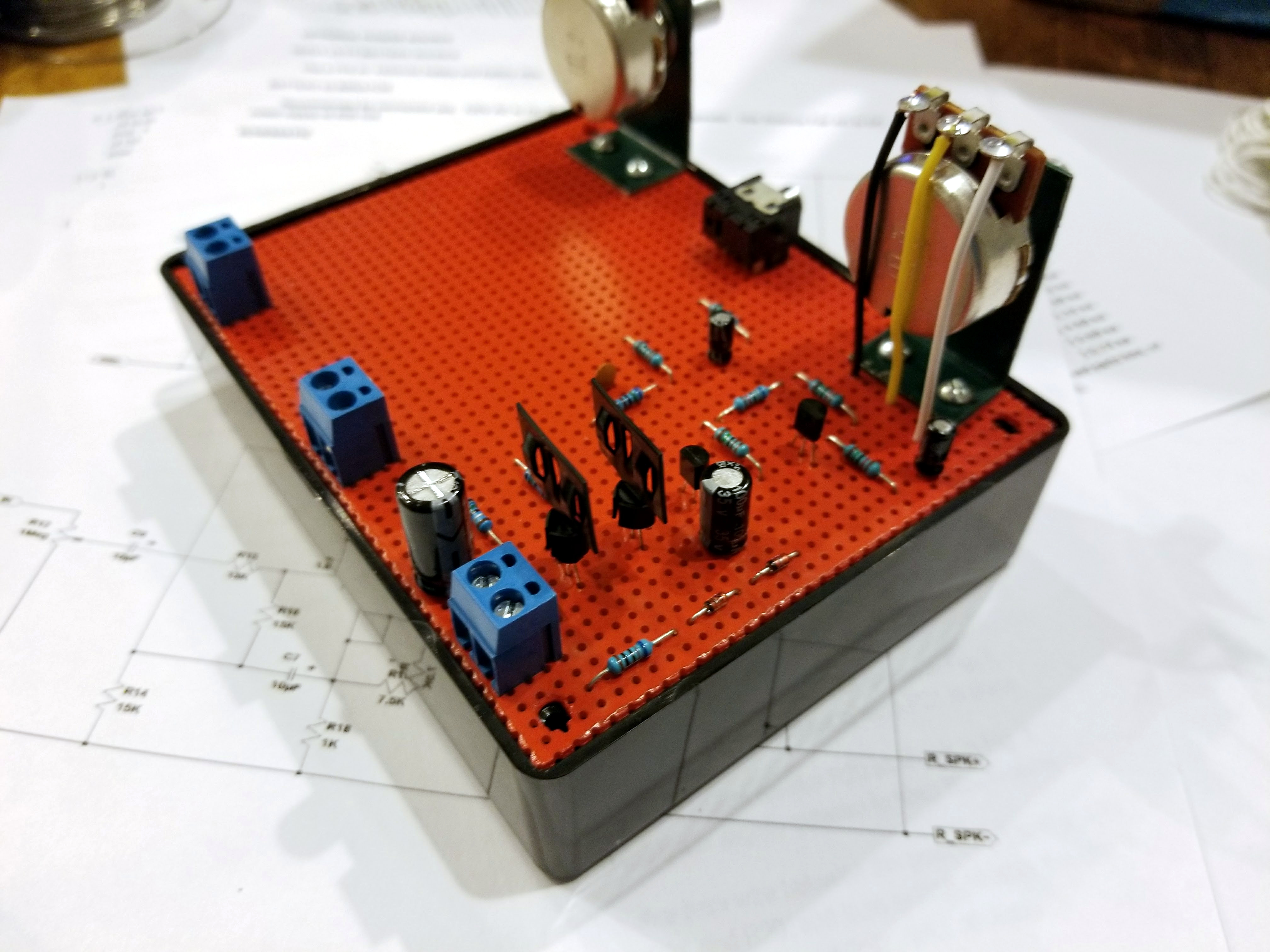
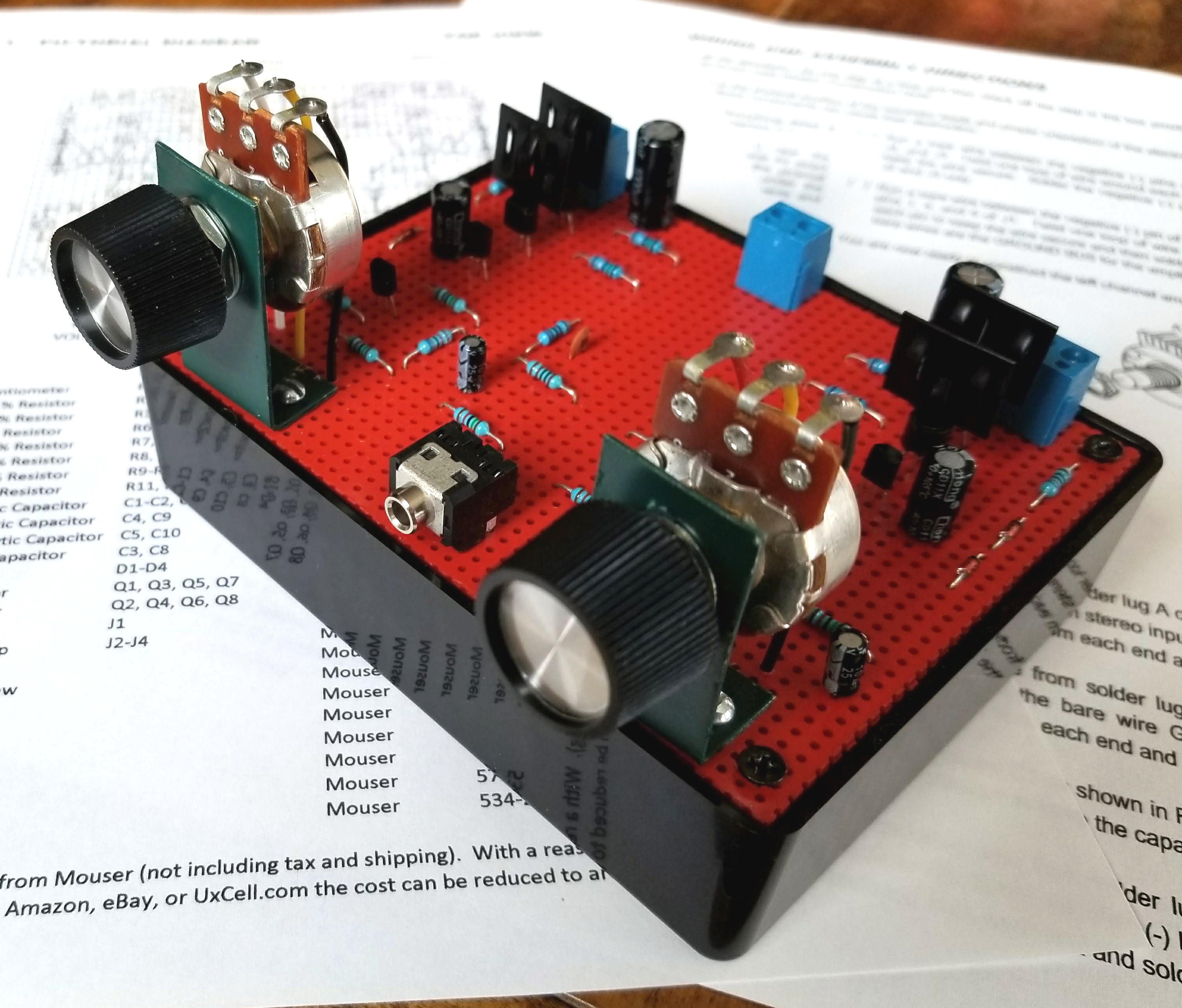
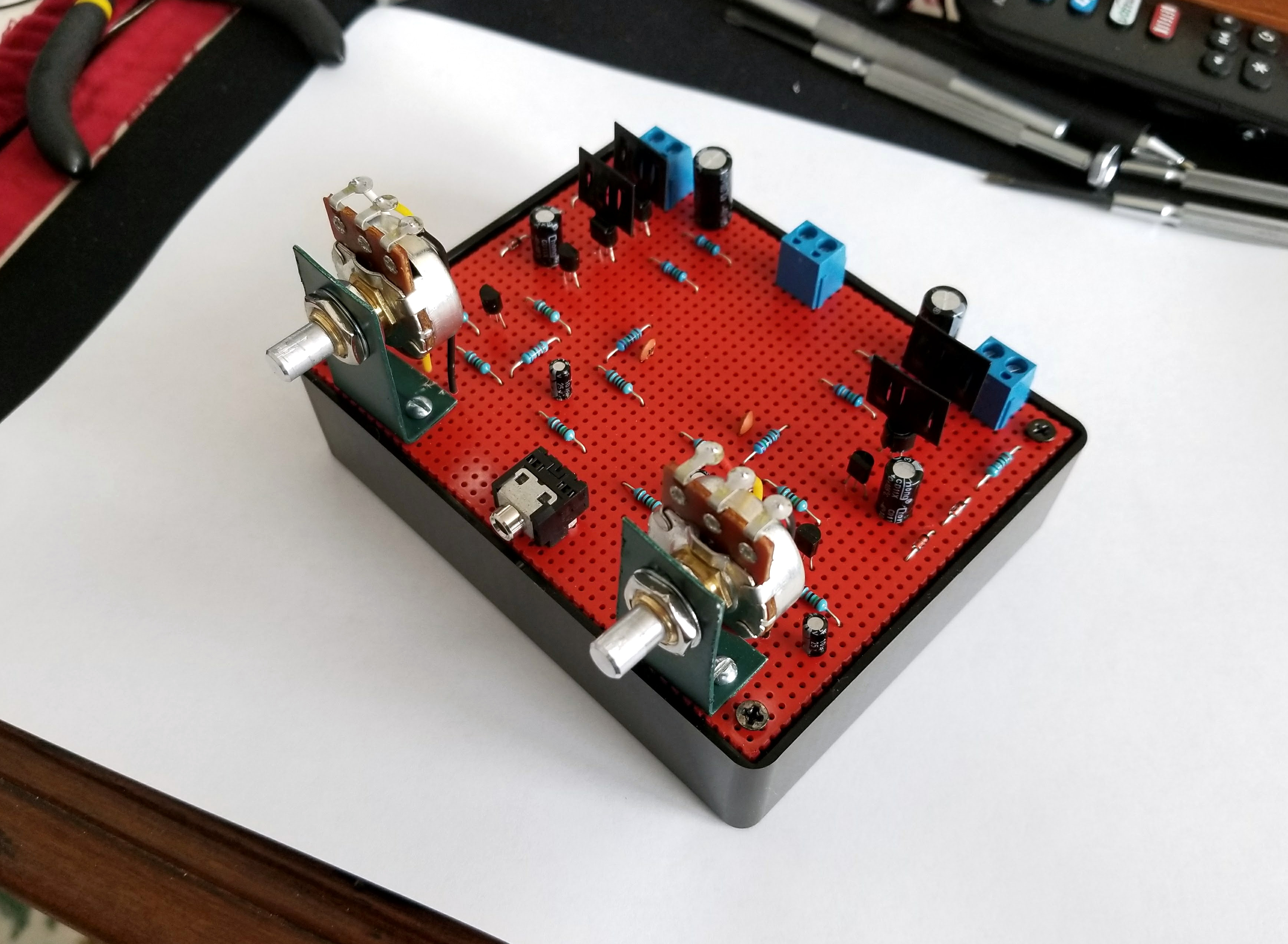
Assembly Photos: Completed Stereo Channel
When completed, the 8 Transistor Stereo Amplifier should look something like the images below. You are now ready to attach the battery and speakers, plug in a sound source, and listen to some tunes on an amp you built yourself.
The assembly manual covers the setup and operation of the amplifier along with some modifications you can make to double the output power if desired. Although for me, 1W was impressive enough.
If hope you enjoyed this article. Thanks for reading!
NetZener