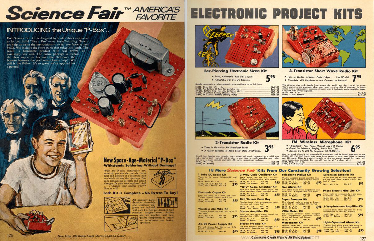
Radio Shack advertised it's first perfboard electronics kits in 1967 and expanded the line in 1968 and 1969. By 1970 there were 26 kits available that included all the parts needed (except the battery) enclosed in a "space age pbox" that served as the packaging and the perforated board that the kit would be assembled on. The 3 Transistor Short Wave Radio project described here is based on the Radio Shack pbox kit of the same name, but it has been updated with silicon transistors and passive components and controls that can be obtained from electronics suppliers on Amazon. When I was a kid I was able to purchase the original 3 Transistor Short Wave Radio kit from the bargain bin of my local Radio Shack long after they were discontinued. I've built the updated radio kit described in this article and believe it works just as well as I remember the original kit did back in the 80's. To make it easy to replicate my work, I've provided illustrations and step-by-step assembly documentation based on the original assembly manual from Radio Shack. I do not make this kit available for sale and I've kept the original branding and copyright notices intact. What I've made available here is strictly for fun and educational purposes. I hope you have as much fun with this project as I did. The original branding, design and documentation are property of Radio Shack.
A little radio theory
If you would like to start building the radio you can skip this section. But if you are interested in knowing how this radio works then by all means, read on!
There are three major receiver types you can build with analog components:
- Tuned Radio Frequency (TRF) receiver
- Regenerative receiver
- Superheterodyne receiver
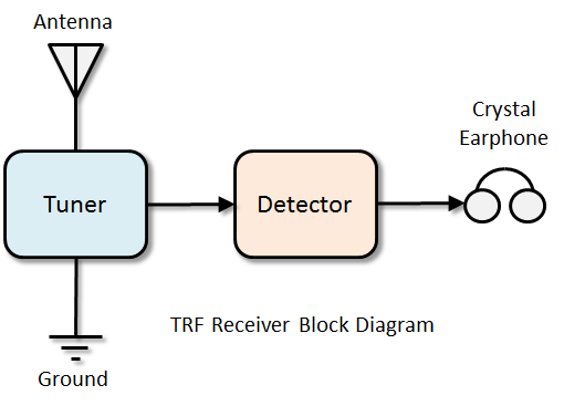
The simplest radio is the TRF receiver which can usually be constructed with only five components and requires no batteries or AC power. A TRF radio is the easiest to build but it is not very sensitive to weak signals and has difficulty distinguishing radio stations broadcasting on channels that are close together. A good antenna and ground connection is required to receive anything other than nearby high-power radio stations. A "crystal radio" is the most common TRF radio that experimenters will build.
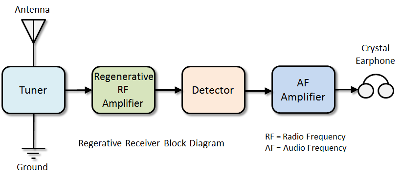
The Regenerative receiver uses some of the same components as the TRF receiver but adds transistors to amplify the radio frequency and audio frequency signals used by the radio station. The Renerative receiver is extremely sensitive to weak signals but it is more complicated than a TRF receiver. It requires battery or AC power to operate, works best with a good antenna and ground connection, and uses two adjustments for tuning in the desired station. The 3 Transistor Short Wave Radio illustrated in this article is a regenerative receiver design.
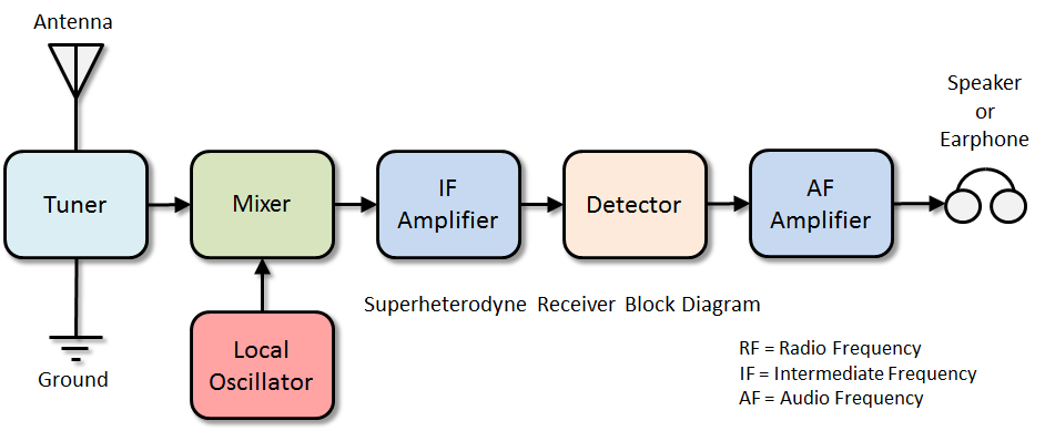
The Superheterodyne receiver uses many of the same components as the TRF and Regenerative receivers but adds special oscillator and amplifier circuits that make tuning into the desired station very easy. This is the type of receiver upon which all modern AM/FM radios are based. The Superheterodyne receiver is sensitive to weak signals and easily distinguishes between stations that are close together. Unfortunately the superheterodyne is the most complicated of the three receiver types and thus the most difficult to build.
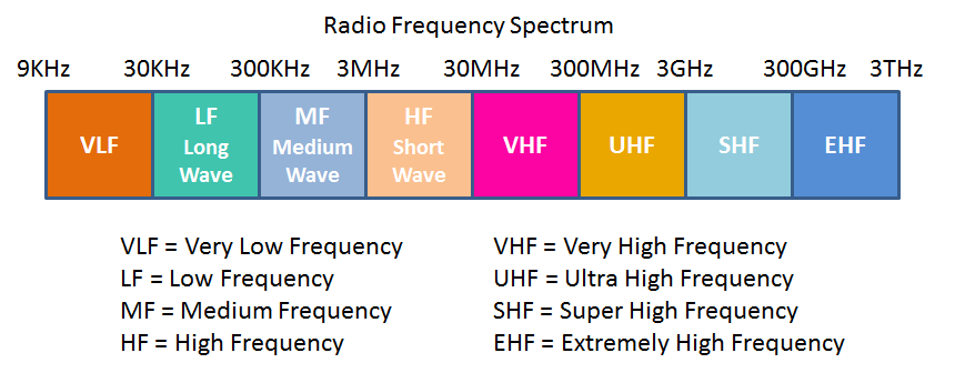
In order for a radio receiver to be useful it needs a transmitter within range that is broadcasting information which can be detected and converted into some useful form of energy (electrical or mechanical). A radio transmitter uses electromagnetic waves to transport information through the ground, the atmosphere, or even across the vacuum of outer space. The properties used to describe these electromagnetic waves include amplitude, frequency, polarization, and direction of propagation. The most important properties for the radios described in this article are amplitude (sometimes referred to as signal strength) and frequency (sometimes referred to as a "channel"). Because electromagnetic waves get weaker with distance, amplitude at the transmitting antenna determines how far away the receiver can be and still detect the information in the broadcast. There are many different frequencies that a radio transmitter or receiver can use depending on the type of information that needs to be broadcast. Some frequencies can pass right through solid objects while others are reflected from stationary or moving objects. Some frequencies can carry voice conversations many hundreds or thousands of miles, while others carry high speed computer data over distances less than 30 feet. To help ensure that radio frequencies are used properly and fairly, all countries regulate who can use what frequency for what purpose. In the United States, the Federal Communications Commission (FCC) is responsible for making and enforcing the rules regulating the use of the radio frequency spectrum. The 3 Transistor Short Wave Radio described in this article is designed to operate in the High Frequency spectrum between 3MHz and 30Mhz.
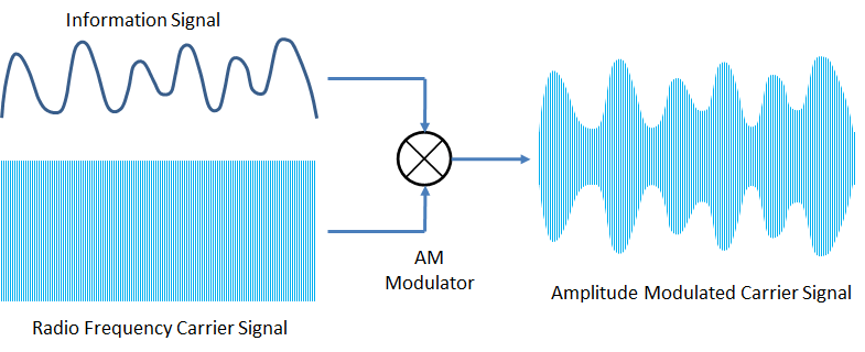
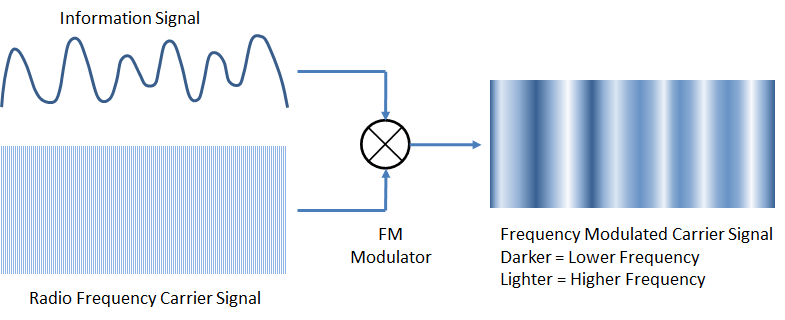
Before a radio station can begin broadcasting, the operator must first determine the frequency that best fits the information it wants to send, and then construct a suitable transmitter and antenna to cover the desired area over which the receivers will be located. Next, the station operator must determine how the information to be broadcast will be superimposed onto the chosen radio frequency. The process of superimposing information onto a radio frequency is called "modulation". There are many different modulation techniques available but the two most popular are Amplitude Modulation (AM) and Frequency Modulation (FM).
With Amplitude Modulation, changes in the amplitude of the information signal causes a proportional change in the amplitude of the radio frequency signal (also referred to as a "carrier signal").
With Frequency Modulation, changes in the amplitude of the information signal causes a proportional shift in the frequency of the "carrier signal".
In most cases, FCC rules and procedures will determine the frequency and modulation that the station will use. Most commercial broadcast stations are authorized to use only one frequency for their transmitter and are issued a station identifier that must be transmitted periodically along with the information they broadcast. The 3 Transistor Short Wave Radio in this article is designed to receive and decode information from Amplitude Modulated (AM) radio frequency carrier signals between 3MHz and 30MHz.
![]()
Not all broadcast stations are limited to a single frequency. For example, Ham radio operators are allowed to broadcast on any frequency within the spectrum set aside for their use. Many Ham operators have multiple transmitters and antennas at their station and can conduct several conversations on different frequencies simultaneously.
A radio receiver performs the opposite function of a radio transmitter. The radio receiver must be sensitive enough to respond to the very small signals created when electromagnetic waves from the transmitting antenna pass by the receiving antenna. Because there are usually many broadcast stations on different frequencies, the radio receiver must be able to select one frequency from the many available. And then the radio receiver must be able to decode the modulated RF carrier and extract the information placed there by the broadcast station.
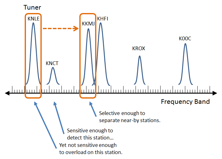
The simplest TRF radio, the crystal AM radio, does not have the ability to amplify a radio broadcast signal. Therefore it's sensitivity is entirely dependent on the quality of the antenna and ground. A long wire antenna hung outside as high as possible with few trees or buildings nearby, combined with a copper ground rod driven at least 24 inches into moist soil works best. Without an antenna the crystal radio usually picks up nothing, so bigger is better.
Regenerative and Superheterodyne radios provide RF and AF amplification and are much more sensitive than the crystal radio. Although both work best with a good antenna, the Regenerative radio can get by with a short wire antenna strung indoors without a ground. And most superheterodyne radios can pick up several stations with only a small internal antenna.
Selecting one frequency from many is the function of the tuner. All radios have some form of tuner even if they are only designed to work on a single frequency. The tuner most often used in the radios covered by this article is known as the Parallel Resonant LC circuit. This circuit is a powerful electronic filter composed of only two components: A capacitor and an inductor connected together in parallel. The perfect Parallel Resonant LC circuit allows one and only one frequency to enter the radio while blocking all other frequencies. The frequency that is allowed to pass through is determined by the following simple formula:
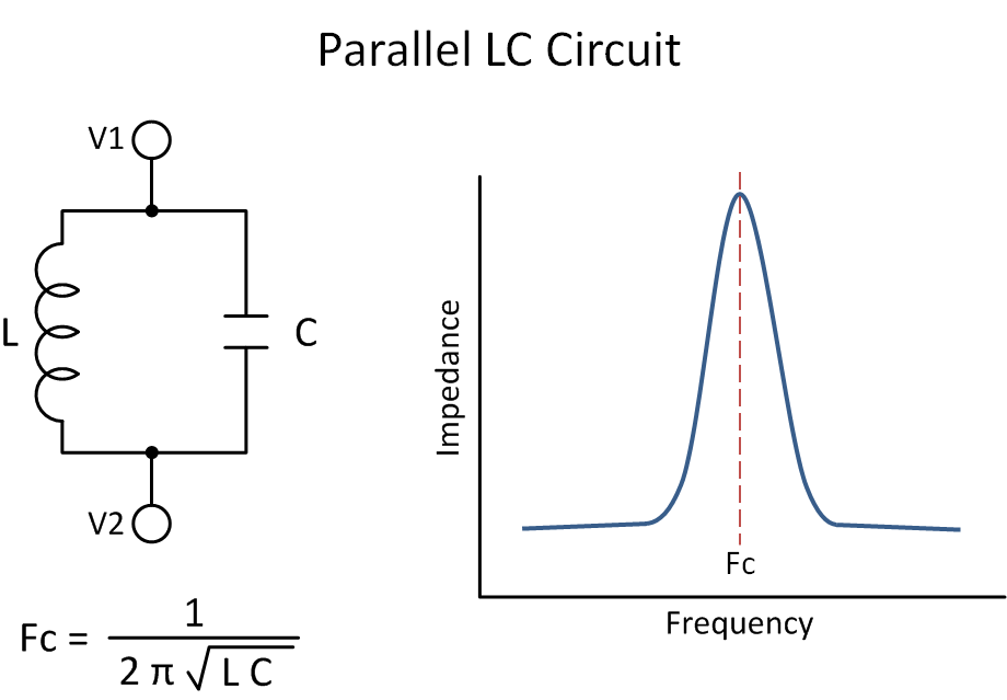
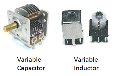
This circuit appears in all radio types, especially the superheterodyne where it performs station tuning and multi-stage signal filtering. As the formula suggests, the center frequency can be changed by adjusting either the inductance L or the capacitance C. An RF tuner typically uses a variable capacitor with a fixed inductor. A tuned RF coupler or filter typically uses a variable inductor and fixed capacitor.
Once a station is selected by the tuner, the received RF signal must be demodulated. Demodulation extracts the information (music, news, data) superimposed in the RF carrier by the radio transmitter. An electronic circuit that performs demodulation is usually called a "detector". A simple AM detector can be constructed with three components as shown below.
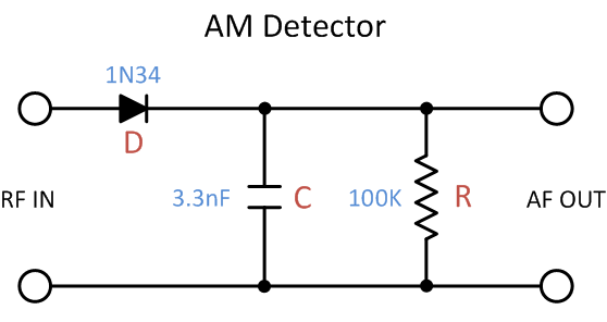
If you review the illustration on AM modulation earlier in this article you will notice that the information signal superimposed on the RF carrier appears in two places: One at the top of the carrier and the other a mirror image at the bottom of the carrier. If both of these information signals were to be extracted simultaneously they would cancel each other out. To prevent this, the diode's job is to eliminate one of the information signals from the carrier. Because a diode allows electrical energy to flow in only one direction, it blocks either the top signal or the bottom signal depending on which direction the diode is installed.
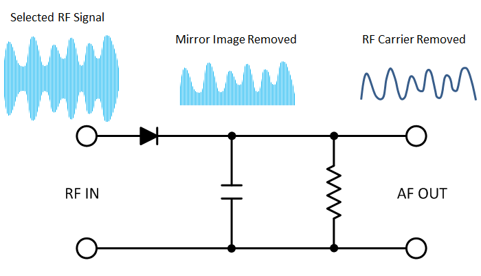
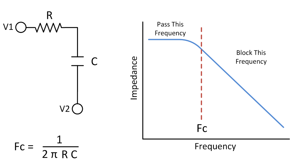
Once the mirror image of the information signal has been eliminated, the last step is to remove the RF carrier. To accomplish that a special circuit called an "RC Low Pass Filter" is needed that will pass the low frequency information signal but block the high frequency RF carrier. A simple RC Low Pass filter used in radio circuits is composed of a Capacitor and a Resistor connected in parallel. The cutoff frequency of the filter is determined by the simple equation below.
The diode detector is used in the TRF, regenerative, and superheterodyne radios. It does not offer the highest sound quality but it is the simplest and least expensive. By assembling the building blocks just described, a simple TRF "crystal radio" can be constructed from just a few simple components as indicated in the schematic below.
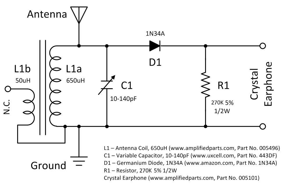
All components can be purchased from Amazon or from the indicated web site. The circuit above, with a good antenna, easily receives several AM broadcast stations within 550KHz and 1700KHz. The sensitivity and selectivity of this TRF radio can be improved by removing the AM detector, filter, and earphone from the L1a coil winding and adding an RF amplifier, AM detector, AF amplifier, and earphone/speaker to the L1b coil winding.
How This Radio Project Came To Exist
Radio Shack began offering 7 electronic kits in 1968 that included all parts, hardware, and instructions in a plastic box. The circuit offered in the kit was assembled by the customer on a perforated prototyping board. The popularity of these kits resulted in an expansion of the product line to 22 kits in 1969, but the perforated board was replaced with a plastic box, called a "pbox", that served as the shipping container, the project breadboard, and the project enclosure all in one. This "space age" pbox turned out to be much easier for young people to work with, reduced the cost of the kit, and made the finished circuit easy to use and interesting to look at.
By the early 80's, however, Radio Shack had become a struggling consumer electronics retailer and most of the kits and component parts were discontinued. While rummaging around in a local Radio Shack store after school I happened to find a 3 Transistor Short Wave Radio kit in a bargain bin, bought it, and assembled it with great pleasure.
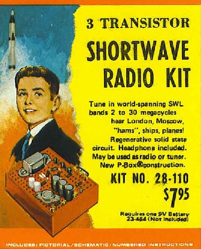
I remember being amazed how well the radio worked using only the 10ft antenna wire supplied in the kit. Unfortunately, I do not remember what happened to the kit after it was completed. Recently I was designing and building a 40 meter SSB receiver and experimenting with software defined radio, and was describing to a friend the complexity of a modern radio receiver. It was then I thought of my old radio kit and how well it was able to operate with only three transistors and a 9V battery. Yes it was fiddly and hard to tune and you had to hold your hand in just the right place to stay in tune, but it could really pick out a long distance station. But then again, maybe my memory was off. I was a kid back then and it WAS the 80's so maybe it didn't really work as well as I thought. If only I could build it again. Alas, pbox kits had fallen into the abyss of the occasional outrageous eBay auction.
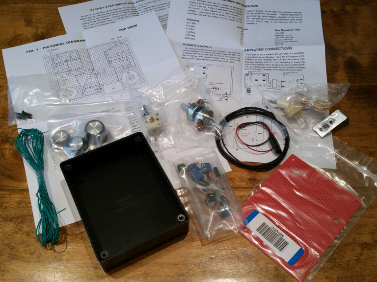
But... If I could find the original schematic perhaps it would be possible to redesign the kit to use silicon transistors. Maybe use some better knobs. I always felt like the original kit could have used some better knobs. And those original spring clips tarnished quickly. I began searching for information on the Radio Shack pbox kits and found a web site run by Steven Vornsand at www.sparktron.com that contained complete information on as many of the kits as were known to exist. A Google search turned up two companies that sold a compact variable capacitor (www.uxcell.com) and crystal earphone (www.amplifiedparts.com) that were critical components for the vintage-like operation of the radio design. So my first step was to reset the bias for the AF amplifier and AM detector which used old germanium transistors. Simulation and prototype construction revealed that the updated circuit with 2N3904 transistors worked slightly better than the expected performance of germanium transistors in the original circuit. The next step was to confirm that the 2N3904 could also be used in the regenerative RF amplifier section without change. Simulation and prototype construction also revealed a better than expected result. For tuning, I discovered that by eliminating the scaling capacitors from the original design the variable capacitor from Uxcell could then be used without having to change the winding dimensions of the air core tuning inductor. Last, I added an earphone jack (the AmplifiedParts earphone comes with a 1/4" plug) and some mini dual-position barrier strips to connect power, inductor, and antenna. Just for fun, I packaged up all the parts like a kit and assembled the final version presented in this article.
After building the radio I've successfully received WWV on 5, 10, 15, and 20 Mhz with good copy. I've picked up all the well-known short wave KW transmitters from around the globe. And I've picked up SSB on 7Mhz and 14Mhz. SSB can be received but the detector is not designed to clearly demodulate it. I remember that happening with the original kit.
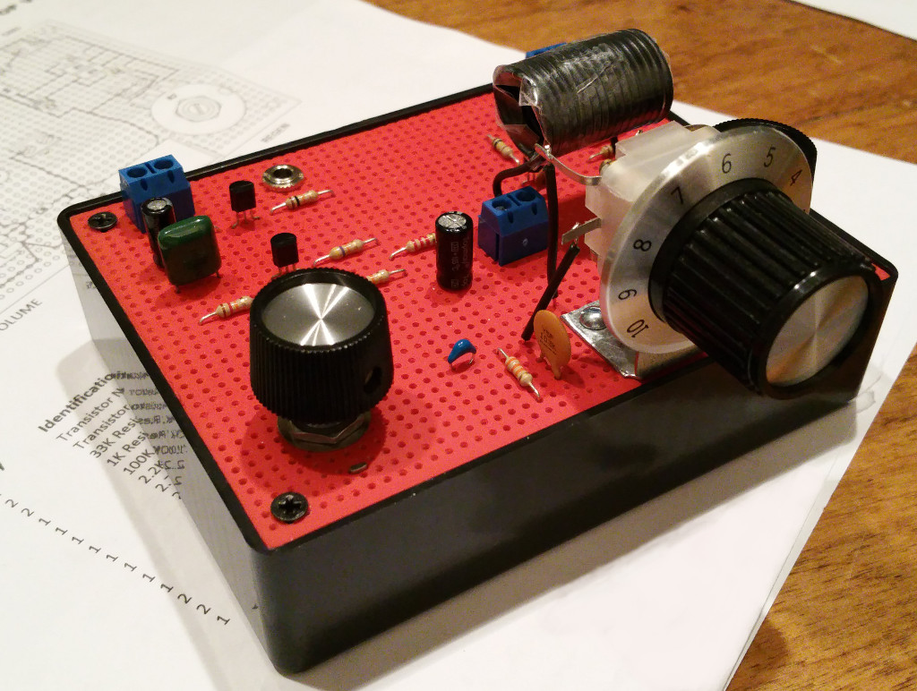
I'm extremely happy with how the 3 Transistor Short Wave Radio looks and how well it pulls in distant stations.
How The 3 Transistor Short Wave Radio Works
The 3 Transistor Shortwave Radio in this article is a regenerative radio designed to tune from 2Mhz through 30Mhz depending on the tuning coil used by the operator. The schematic for the radio with the major building blocks highlighted is illustrated below:
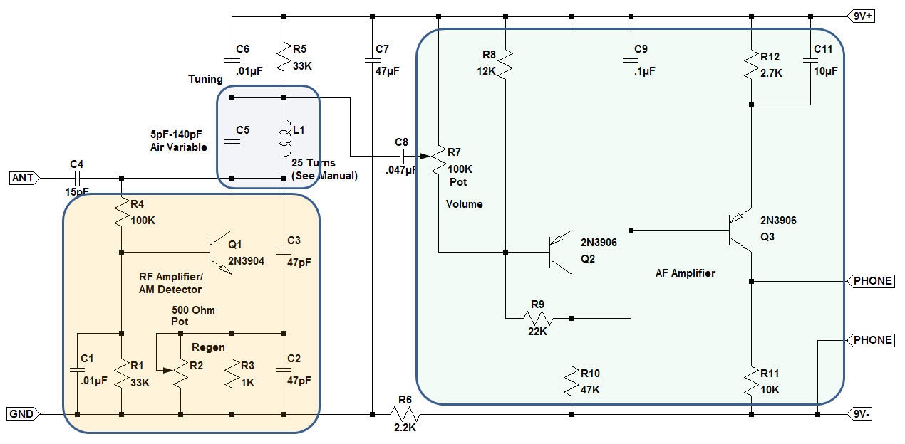
Variable capacitor C5 and tuning coil L1 comprise the Tuning section. L1 is a fixed inductor wound according to the assembly manual for the frequency band of interest.
The RF Amplifier/AM Detector section is actually a Colpitts Oscillator with an added variable resistor R2 that serves as the regeneration control. Resistors R1 and R4 provide base voltage to Q1 so that it's collector is fixed at approximately 3V. This collector voltage was chosen so that the RF Amplifier/AM Detector will continue to operate properly as the 9V battery reaches the end of it's life. The large values of R1 and R4, and the bootstrap bias configuration they are connected in, were chosen so that the RF Amplifier/AM Detector will have a high input impedance which improves the selectivity and sensitivity of the radio. Capacitors C1 and C6 were included to bypass RF around resistors R1 and R5 respectively which improves the gain of the RF Amplifier circuit. The collector output of Q1 is fed back to the emitter of Q1 through capacitors C2 and C3. Normally this positive feedback would cause the RF Amplifier/AM Detector to continuously oscillate. However the regeneration control provides an adjustable amount of negative feedback at the emitter of Q1 that counteracts the positive feedback. By carefully adjusting the amount of negative feedback on the emitter of Q1, the circuit can be made to provide extremely high gain just before oscillation occurs, and at the same time remove most of the RF Carrier signal and the unwanted image of the audio signal. This behavior is the reason the regenerative radio works so well.
The AF Amplifier is a simple two-stage direct coupled Common Emitter amplifier for driving the crystal earphone. Transistor Q2 provides a gain of approximately 5 and together with R10 and C9 performs additional filtering of the carrier signal. Transistor Q3 provides a gain of approximately 100 (the transistor current gain at .5mA). Capacitor C11 is provided to bypass audio frequencies around resistor R12 and improve the gain of Q3. Together, Q2 and Q3 provide an additional gain of approximately 500 after the RF amplifier. The value of R12 was chosen so that the collector voltage of Q3 would be set at approximately 1/2 battery voltage which ensures that the Detector and AF Amplifier will continue to operate properly as the 9V battery reaches the end of it's life.
Capacitor C7 and resistor R6 are wired together as a simple RC Low Pass Filter to prevent RF noise at the RF amplifier from bleeding into the AF amplifier via the battery connections.
How to build the 3 Transistor Short Wave Radio
To build the radio described in this article, you will need the revised assembly manual I've created which include the design and layout changes I've made.
> Click Here to obtain the assembly manual <
Here's a few other things:
- The transistors for the radio can be purchased from Amazon.com or Radio Shack (assuming they are still in business in your area). I highly recommend the excellent Joe Knows Electronics semiconductor kit. It includes the transistors you need for this radio project and over 150 different types of transistors and diodes for just $22. And it includes a set of documents that are really good reading for the beginner. Check out www.joeknowselectronics.com. You will not be sorry.
- The resistors for the radio kit can be purchased from Amazon.com or Radio Shack. Radio Shack has a good selection of 1/4W resistors in a big 500 piece bundle for about $15.00 if you have a store nearby. Joe Knows Electronics also has a nice 800 piece package of 1% resistors for $12.00 if you don't mind ordering online. Joe's is a really good and well organized kit even if 1% resistors are a bit of tolerance overkill for this radio project.
- I strongly recommend ordering NP0 ceramic disk capacitors from www.mouser.com or www.digikey.com as they will far outperform most anything you can get on Amazon.com. The Joe Knows Electronics capacitor kit is an extremely good buy for every other capacitor at 645 pieces for $13.00. Don't bother with Radio Shack for capacitor kits as they are mostly junk values you will never use.
- I purchased several crystal earphones from www.amplifiedparts.com on Amazon.com and they work great despite the poor reviews. Whatever quality problem they had in the past seems to have been ironed out.
- The variable capacitor (and a lot of other rather old and interesting parts) can be found at www.uxcell.com which seems an unlikely domain for radio stuff but they do have a lot of radio stuff that's interesting. I've created a diagram of the variable capacitor >> here << that will help you figure out how to wire it in the radio.
- The case for the kit I built is a Hammond 1591GSBK ABS Project Box from Amazon.com with a piece of vector breadboard cut to fit on the top and spray painted with high temperature automotive flat red. I like the look of red on black, and the red color of the breadboard matched the red color of the original pbox kit. It's completely up to you how you want to house and color the kit you build.
- The knobs I used are Radio Shack knobs I've had in inventory for decades. Use anything you think is cool that will fit on the pot/varicap shafts.
- You will need to be creative on how you mount the variable capacitor on the vector board. I used a piece of 1/32" sheet metal cut to size with a Dremel tool grinding wheel and then drilled the holes to mount the variable capacitor with a power drill. Then I bent the end of it 90 degrees to form an L shape. This is the most challenging part. But I am sure you can overcome this minor obstacle being the resourceful person you naturally are.
- You will need to be creative on how you mount the tuning knob to the variable capacitor. The shaft on the varicap is only about 1/4" long so you will need something to extend it. I found a plastic cylinder with a hole drilled through it that was about 1" long at my local Ace hardware store. They have a really nice selection of odd hardware that is very useful. Again... be resourceful and look for a solution in unexpected places that will work. That's some of the fun of a project like this.
- The 2-position barrier strips are available from Radio Shack in a pack of four. These are a great value at the price so if your local Radio Shack hasn't yet been turned into a Sprint cell phone shop you should definitely buy all of the packs on the peg. I know I did.
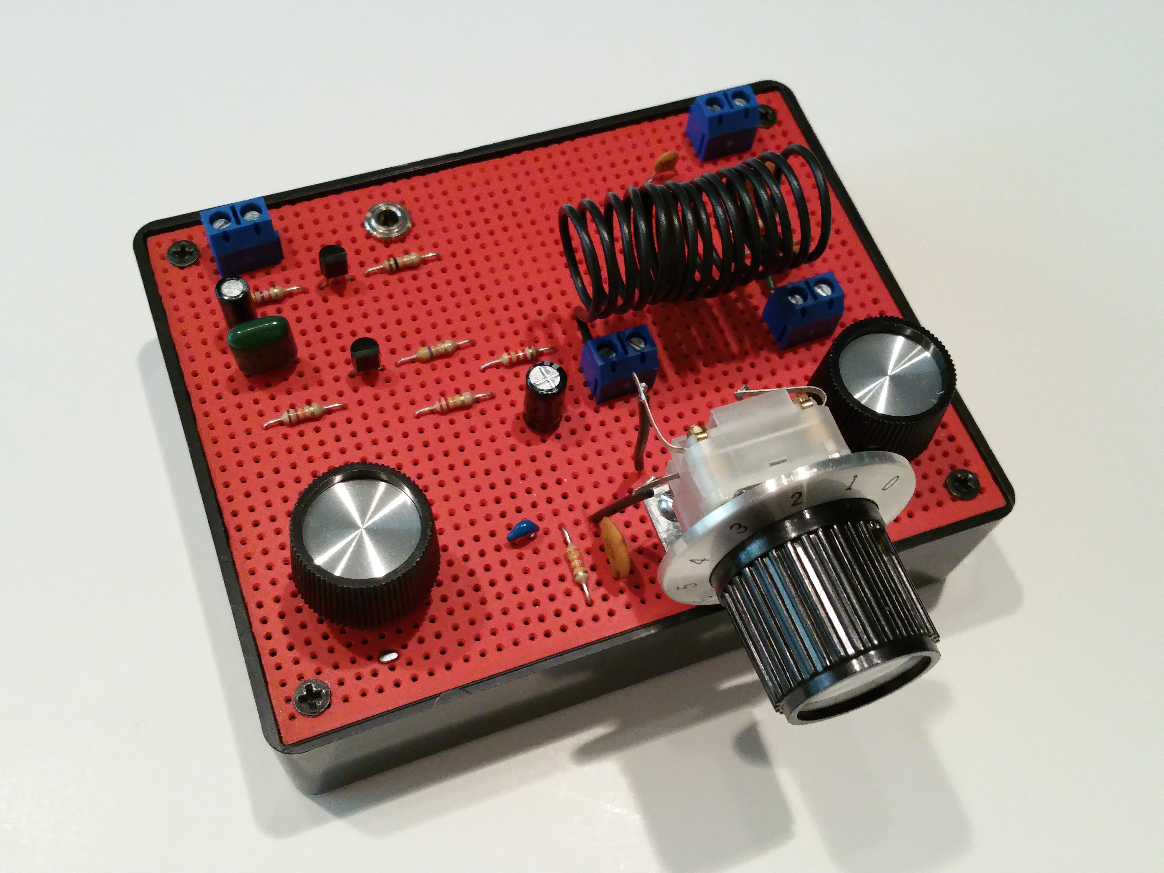
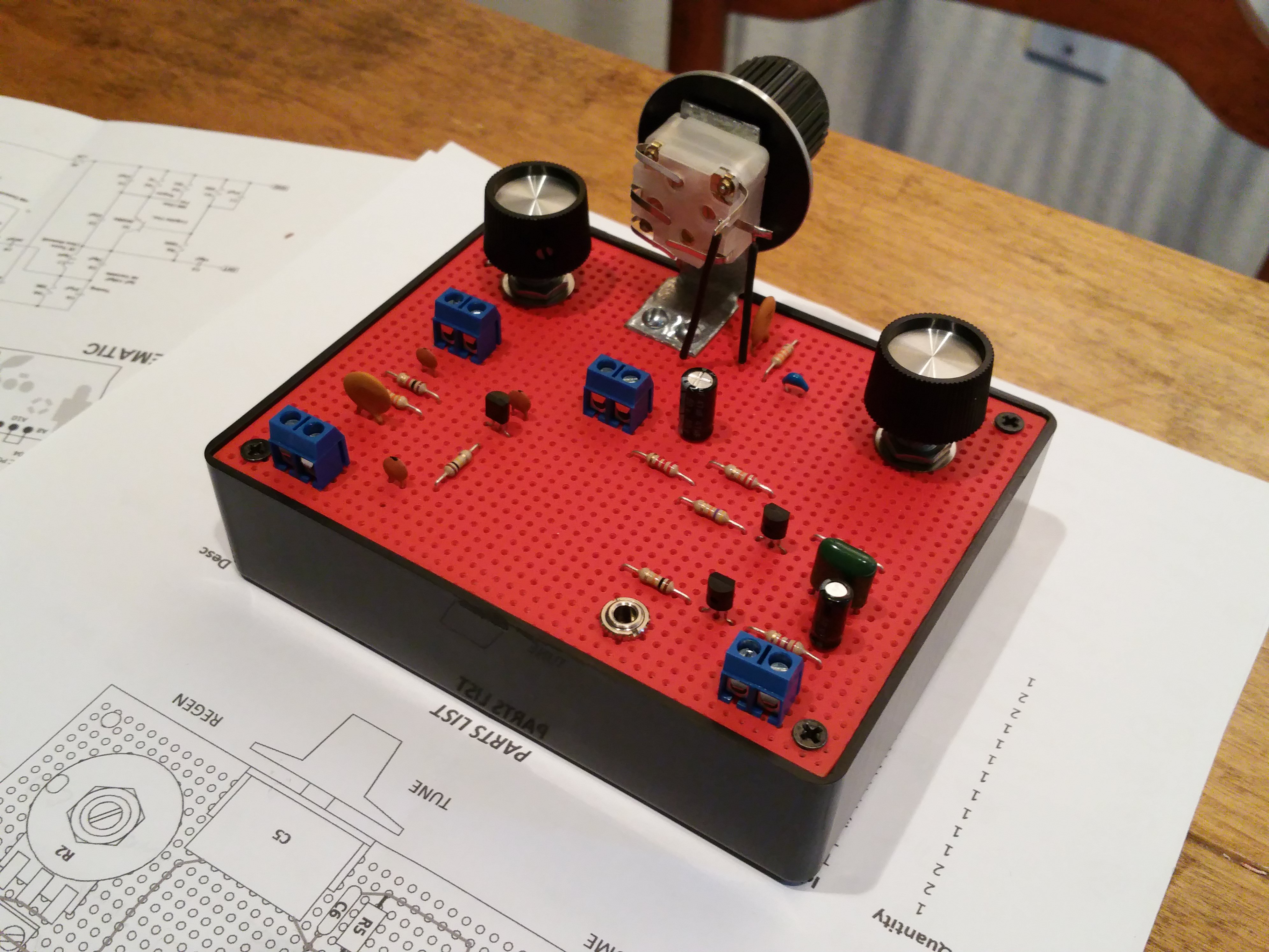
When it comes to wiring, try to be as neat as I've indicated in the assembly manual. You don't have to be the world's best soldering artist but there's no good reason to do the work half-way. Go all out and make your radio look as good as you can. Here's what mine looks like from below:
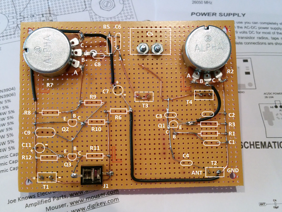
In hopes of helping out, I've included a parts legend so that you can see where the components are supposed to go when the breadboard is turned over. When it comes to RF work, keep it short and keep it neat is good advice. Do what I did above and your radio will exceed your expectations.
One final note:
Any radio is only as good as it's antenna and the environment it is in. In my area, everybody and his extended family has a wireless router, 4 cell phones, three LCD TV's, and who knows what else making more electronic noise than a chicken coop surrounded by a family of foxes (Sorry, I couldn't help but include at least a little bit of classic Southern humor). A good antenna as described in the Assembly Manual is essential for getting the best performance from this radio project. I brought my radio out to rural Anacoco, Louisiana and attached a 10ft wire antenna to a clothes line, and received more stations than I had time to listed to. I was amazed at how well this little radio performs. If you don't know what a clothes line is, you probably don't live in rural Louisiana, and that's totally OK. Lets just say an electrically quiet environment also helps.
I hope you have as much fun working on this project as I did. Good luck and good listening!